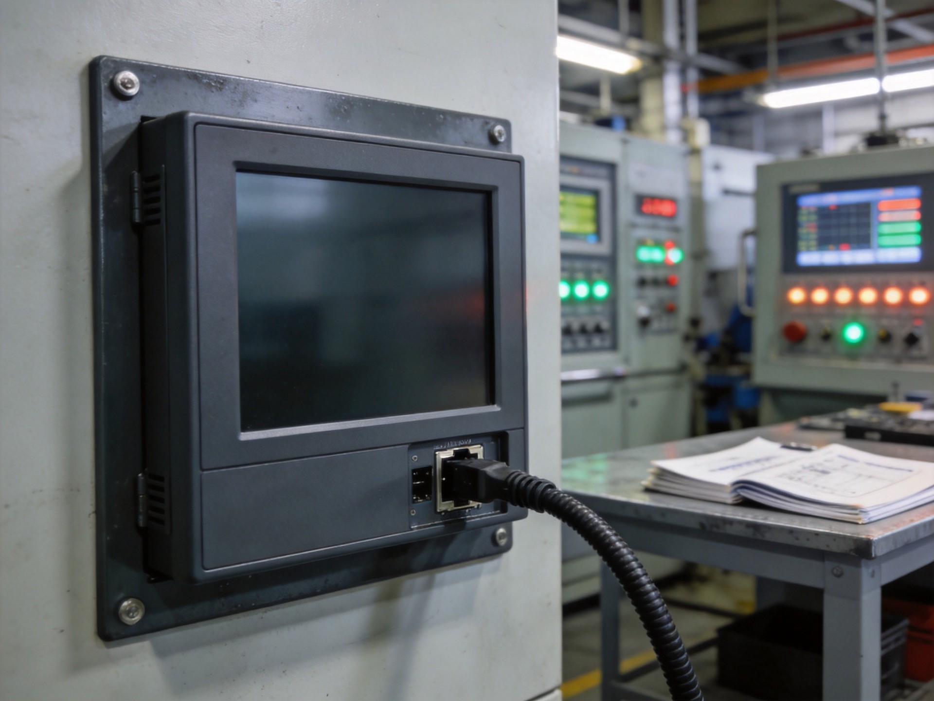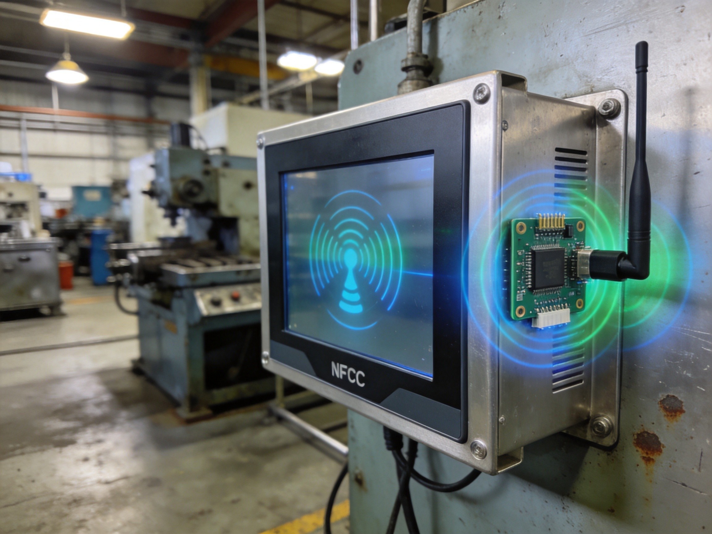
USB ports are the most accessible interfaces on any industrial panel PC, and that accessibility makes them the most vulnerable. Every time an operator plugs in a keyboard, scanner, or maintenance drive, the port faces electrostatic discharge, overcurrent conditions, and the wear of thousands of insertion cycles. In a factory, static electricity builds up on personnel and equipment, and a single ESD event can release tens of kilovolts. When that discharge reaches internal circuitry through a USB port, damage ranges from subtle data corruption to catastrophic controller failure. Understanding protection and building redundancy is essential for any deployment where downtime carries a production cost.
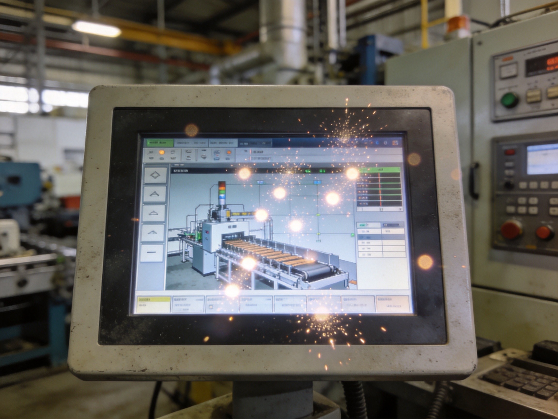
The physics of ESD damage is straightforward. A static charge discharges through the first conductive path it finds. If that path is a USB connector, current travels through signal lines and power rails with peak currents exceeding 30 amperes and nanosecond rise times. Semiconductor junctions were never designed to handle this energy. The result is often a latent failure: the device works but degrades until a second event finishes the job weeks later. For a KOXIAN panel PC on a production line, latent failures are more dangerous than immediate ones because they evade diagnosis and create intermittent problems that frustrate operators and maintenance teams alike.
ESD Protection: The First Line of Defense
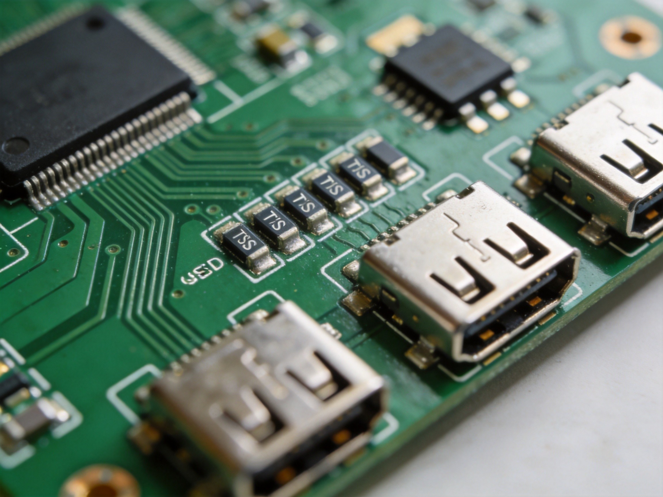
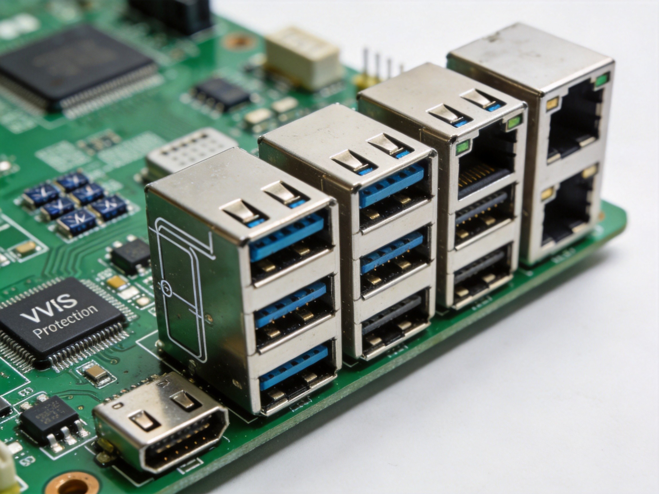
The primary defense is a protection circuit at the entry point. TVS diode arrays on USB data lines and power rail act as voltage clamps. Under normal conditions, they are invisible to the signal. When a spike exceeds the threshold, the TVS diode shunts the discharge to ground within picoseconds. A USB 2.0 protection scheme specifies TVS diodes rated for IEC 61000-4-2 Level 4, surviving 8 kV contact and 15 kV air discharges. For USB 3.0, the challenge is protecting high-speed differential pairs without parasitic capacitance degrading signal integrity, requiring careful PCB layout.
Overcurrent Latch-Up: The Hidden Threat
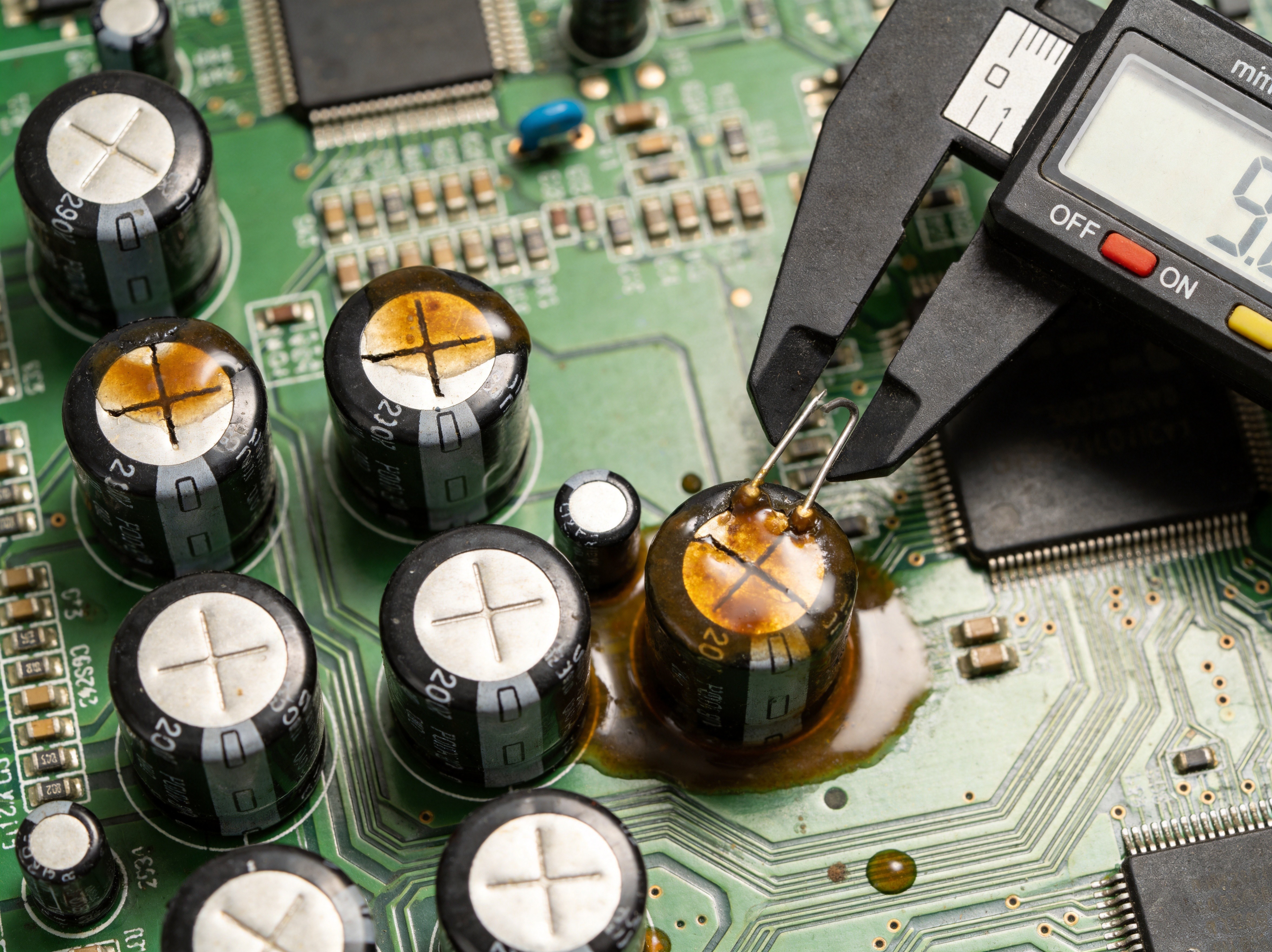
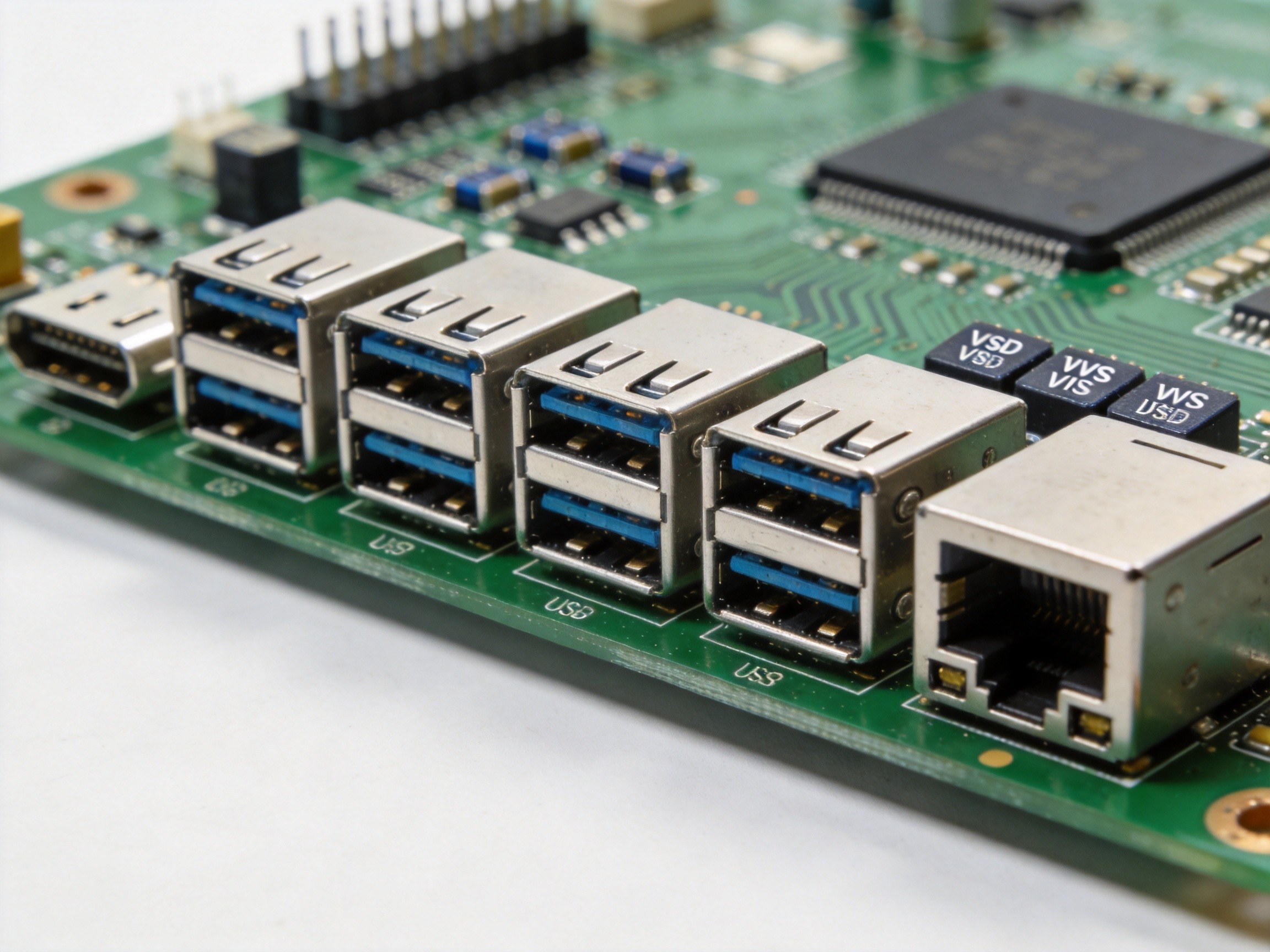
Overcurrent conditions are equally destructive and more common than ESD. A shorted cable, a malfunctioning peripheral, or a faulty regulator can trigger an overcurrent event. When the USB power rail exceeds its limit, thermal stress causes latch-up: a parasitic thyristor creates a low-impedance path between power and ground that persists until the device is power-cycled or destroyed. Protection combines current-limiting power switches and polymeric positive temperature coefficient fuses. The switch monitors current and shuts off the port at 500 mA for USB 2.0 or 900 mA for USB 3.0. The polymeric fuse provides secondary protection: if the switch fails, the fuse increases resistance by orders of magnitude, disconnecting the load until the fault clears. KOXIAN panel PCs incorporate both layers, preventing a single faulty peripheral from taking down the entire system.
Redundancy Strategies for Mission-Critical Deployments
For deployments where panel PC failure means a production stoppage, protection circuits alone are not enough. A dual-unit configuration with two identical panel PCs sharing peripherals provides the safety net. If the primary unit experiences a USB port failure, the secondary takes over and production continues with minimal interruption. Switching can be manual or automated through heartbeat monitoring. USB peripherals connect through a switching hub that redirects signals without re-cabling. For continuous-process industries where unplanned downtime costs thousands of dollars per hour, this is a straightforward business decision.
Designing for Long-Term Reliability
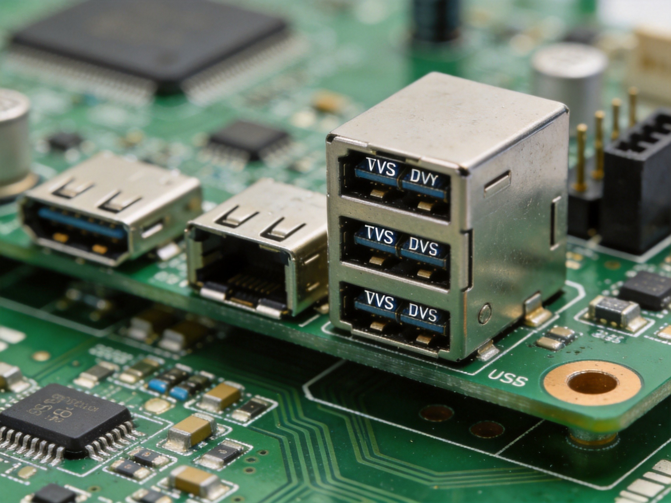
Reliability starts with design decisions. The USB connector must use gold-plated contacts rated for tens of thousands of insertion cycles. The connector shell must be mechanically anchored to the enclosure, not just soldered to the PCB, so physical stress transfers to the chassis. The USB subsystem should be isolated from the main power plane through dedicated voltage regulators, preventing a USB rail fault from propagating to the processor. Every protection circuit must be tested in production through automated equipment applying calibrated ESD pulses and measuring residual voltage at protected nodes. When these practices are followed, USB ports become reliable interfaces, surviving years of daily use in harsh factory environments.
USB port failures are preventable. Properly designed ESD and overcurrent protection, verified against industry standards, combined with system-level redundancy, transforms USB ports from the most vulnerable interface into one of the most resilient. When operators expect peripherals to work every time, that reliability is not a feature. It is a requirement.