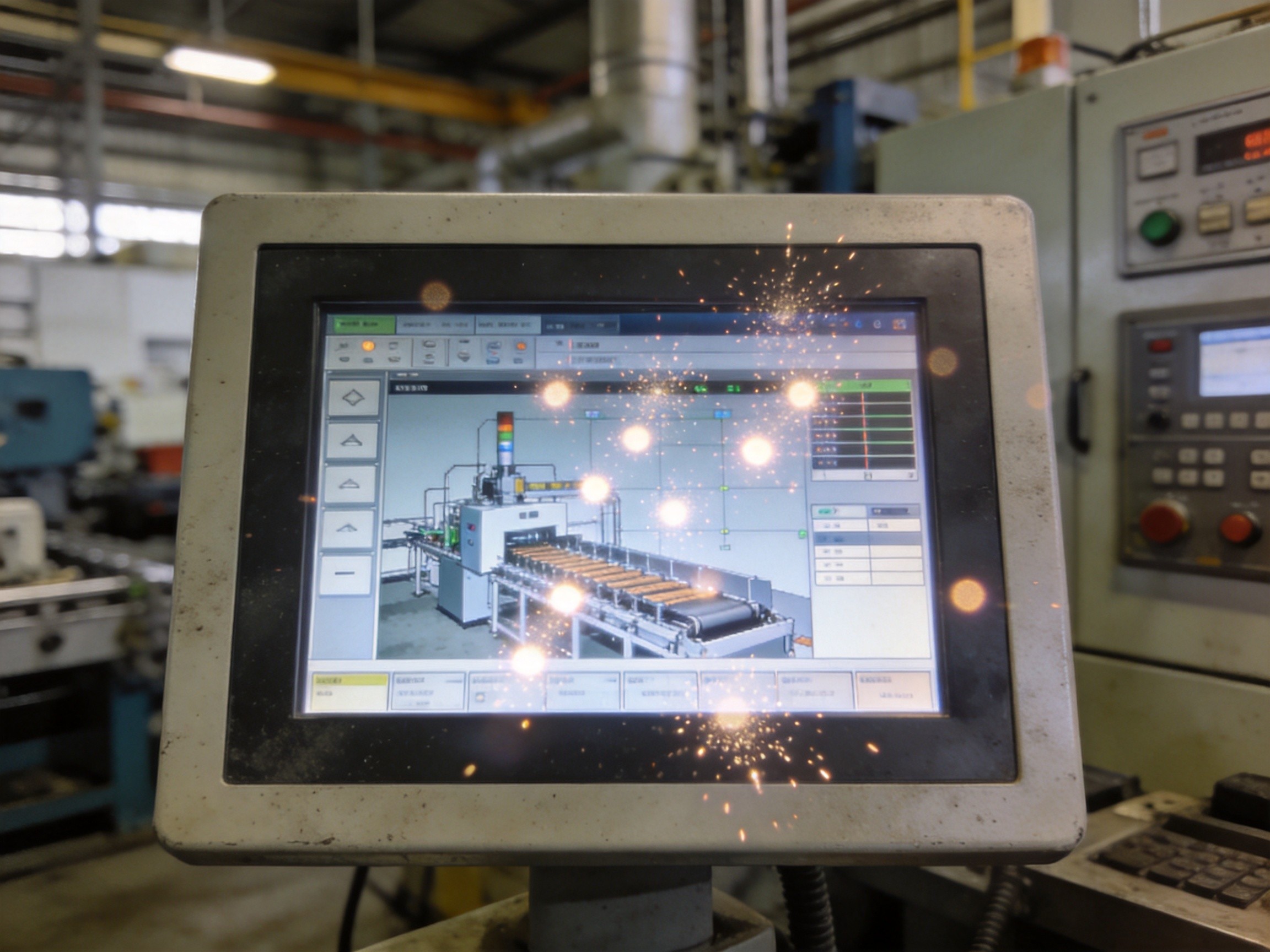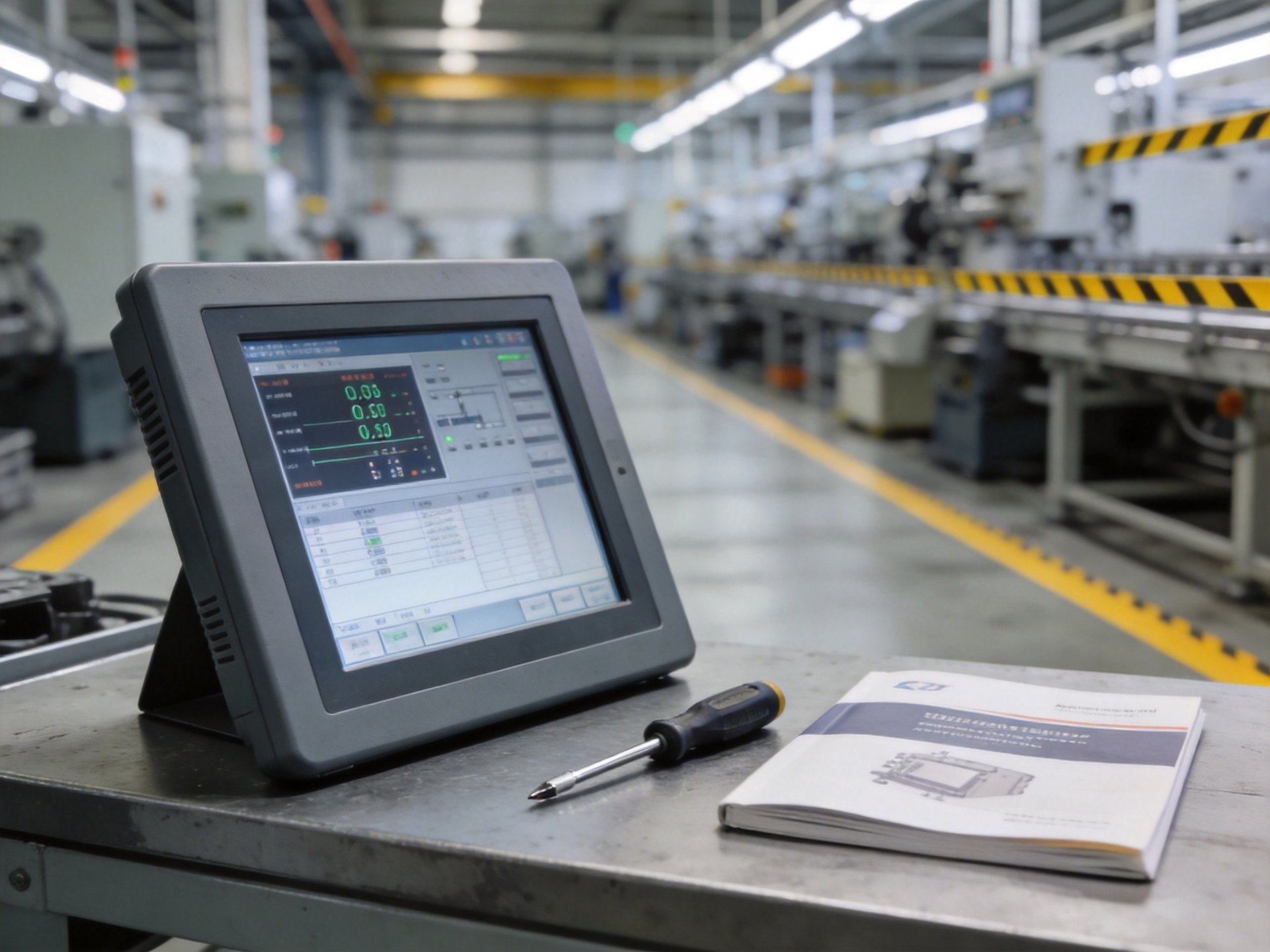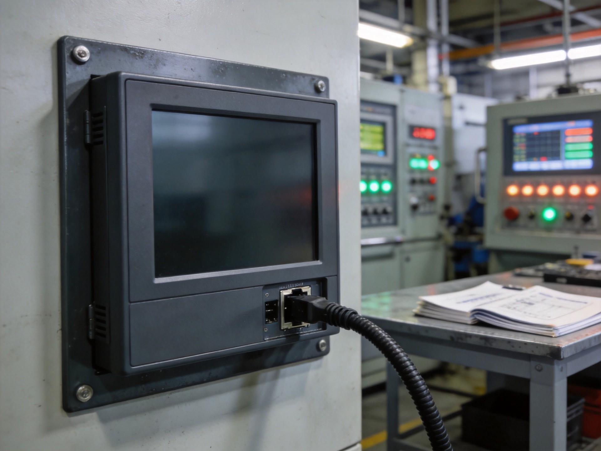
Every watt of electrical power consumed by an industrial panel PC eventually becomes heat. In a sealed, fanless enclosure—the design required for dust-laden factories, food processing cleanrooms, and outdoor installations—that heat has nowhere to go except through the chassis walls. When heat generation exceeds dissipation capacity, internal temperatures rise until components throttle, fail, or enter thermal runaway. Field failure analyses consistently identify thermal stress as the leading cause of premature panel PC degradation in industrial environments, ahead of vibration, contamination, and electrical transients. Understanding the three pillars of passive thermal management—heat pipe design, thermal interface materials, and enclosure geometry—is the difference between a panel PC that runs for a decade and one that fails within its first summer on the factory floor.
The Physics of Thermal Runaway in Sealed Enclosures
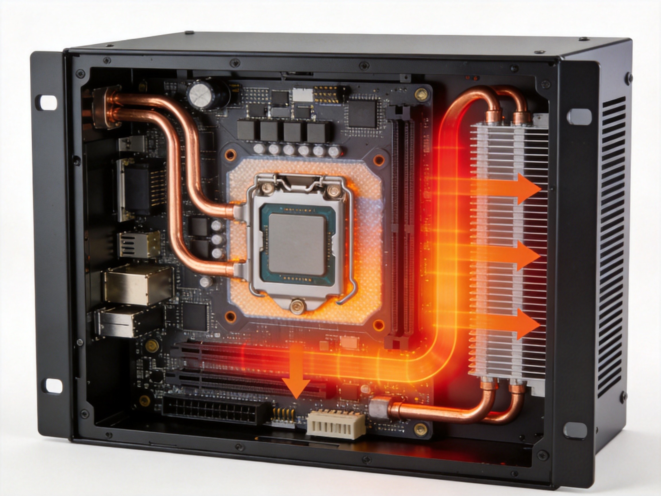
Thermal runaway in electronics follows a self-reinforcing cycle. As junction temperatures rise, semiconductor resistance increases, generating more heat and further increasing resistance. The cycle accelerates until the component either throttles or fails catastrophically. In a sealed enclosure, the absence of forced convection exacerbates this cycle. The only heat transfer mechanisms are conduction through solid materials and natural convection at the external chassis surface. The internal air gap between heat-generating components and the enclosure wall acts as an insulator—still air has a thermal conductivity of approximately 0.026 watts per meter-Kelvin, roughly 8,000 times worse than copper. This is why simply placing a heatsink inside a sealed box is insufficient. The thermal path must be engineered from the silicon die to external ambient air, with every interface optimized to minimize thermal resistance.
Heat Pipe Design: The Engine of Passive Cooling
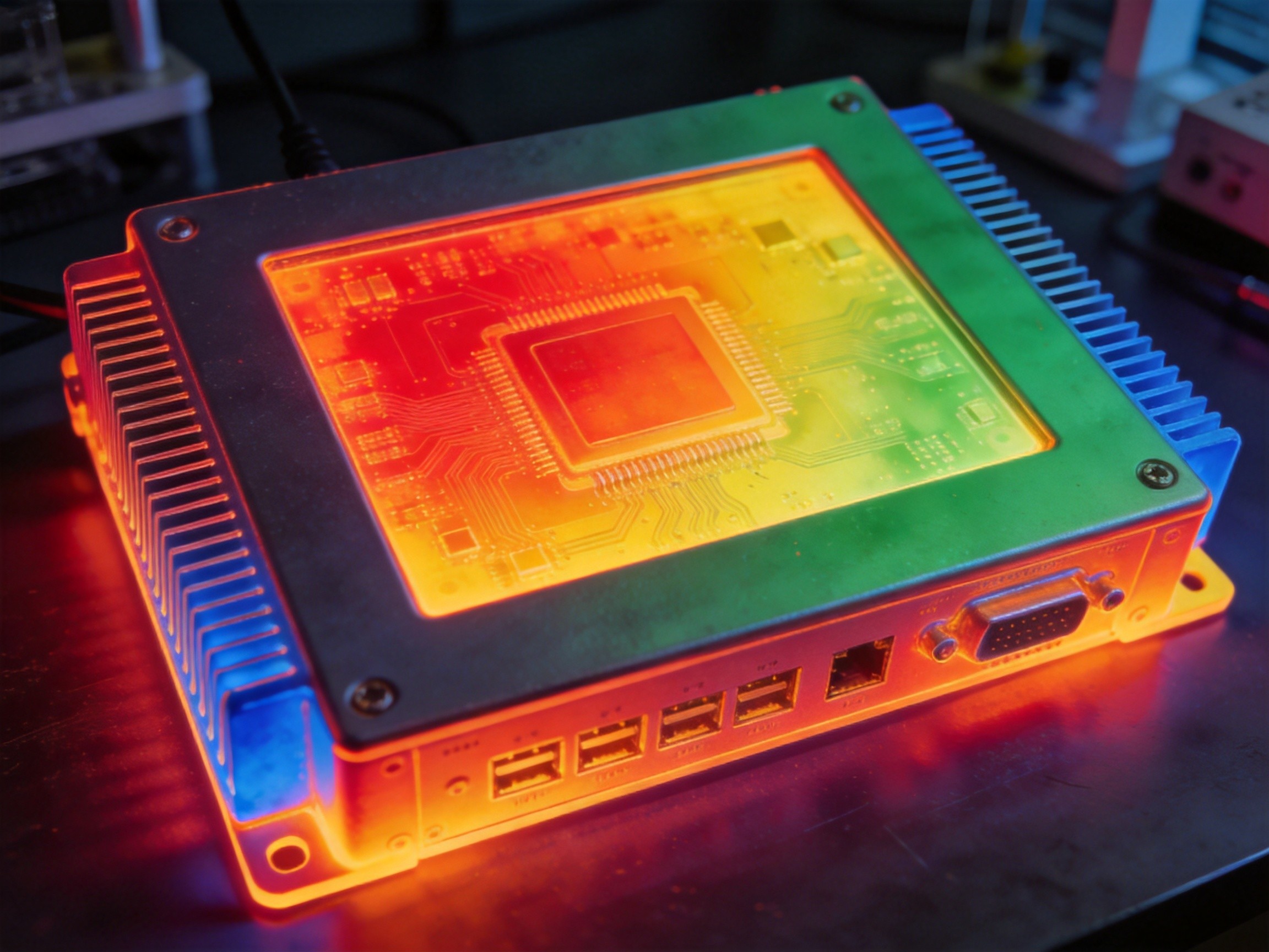
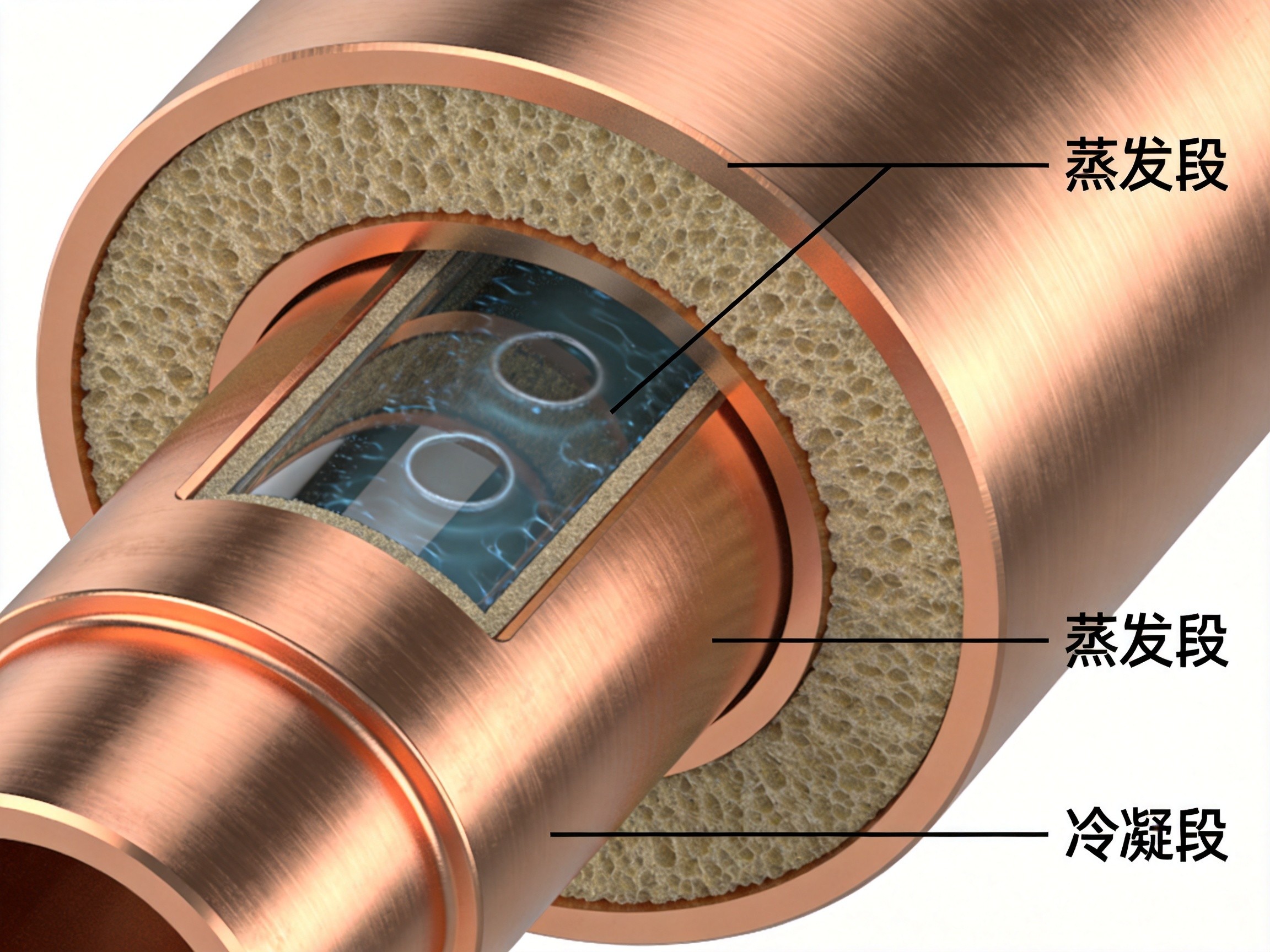
Heat pipes are the workhorses of passive thermal management in industrial panel PCs. A heat pipe is a sealed copper tube containing a small amount of working fluid under partial vacuum. When one end is heated, the fluid vaporizes and travels to the cooler end, where it condenses and releases latent heat. The condensed liquid returns to the hot end via capillary action through a wick structure. This phase-change cycle transports heat hundreds of times more efficiently than a solid copper rod of the same dimensions. The critical design parameters are working fluid selection, wick structure type, and pipe orientation relative to gravity. Sintered powder wick structures provide the best performance against gravity, which matters when a panel PC is mounted vertically. KOXIAN panel PCs use customized heat pipe assemblies with sintered wick structures and multiple independent thermal paths, ensuring a single heat pipe failure does not disable the entire cooling system.
Thermal Interface Materials: The Micron-Scale Gap
No matter how flat a CPU lid and heatsink base appear, at the microscopic level they are surfaces of peaks and valleys that trap air. Thermal interface material fills these gaps, replacing low-conductivity air with a higher-conductivity compound. The choice of TIM has an outsized impact because the thermal resistance at the interface can easily exceed the resistance through the entire heatsink body. Phase-change TIMs, which soften and flow at operating temperatures, provide the best long-term performance in panel PC applications by accommodating thermal expansion and contraction during daily power cycles. Traditional silicone-based greases suffer from pump-out—the mechanical pumping action that squeezes grease out of the interface gap over thousands of thermal cycles. Graphite-based pads offer an alternative with no pump-out risk, though their conductivity is lower than premium phase-change materials. KOXIAN panel PCs use calibrated spring-loaded mounting systems that maintain consistent interface pressure from cold startup at minus twenty degrees Celsius to sustained operation at seventy degrees Celsius.
Enclosure Geometry and External Fin Design
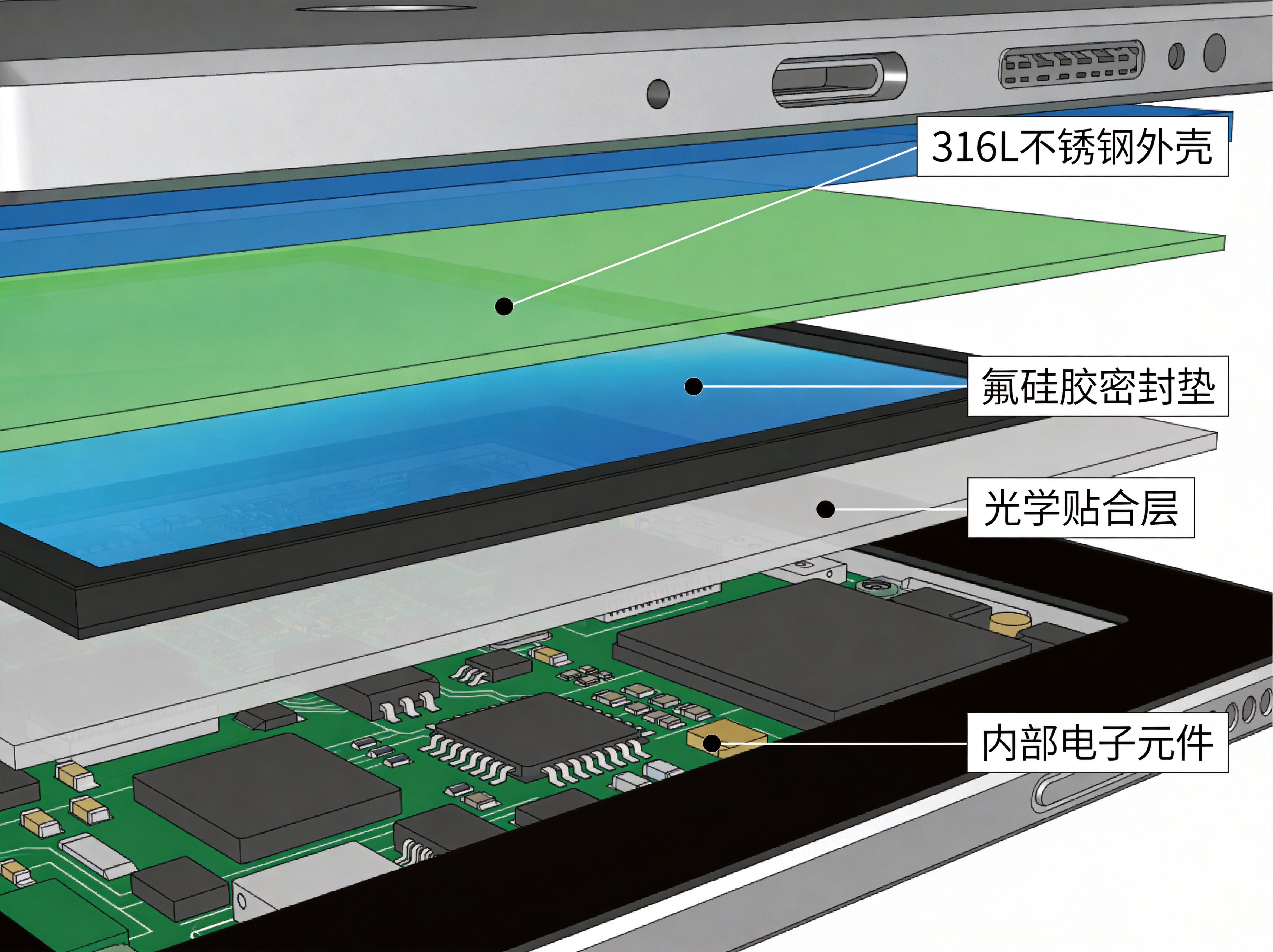
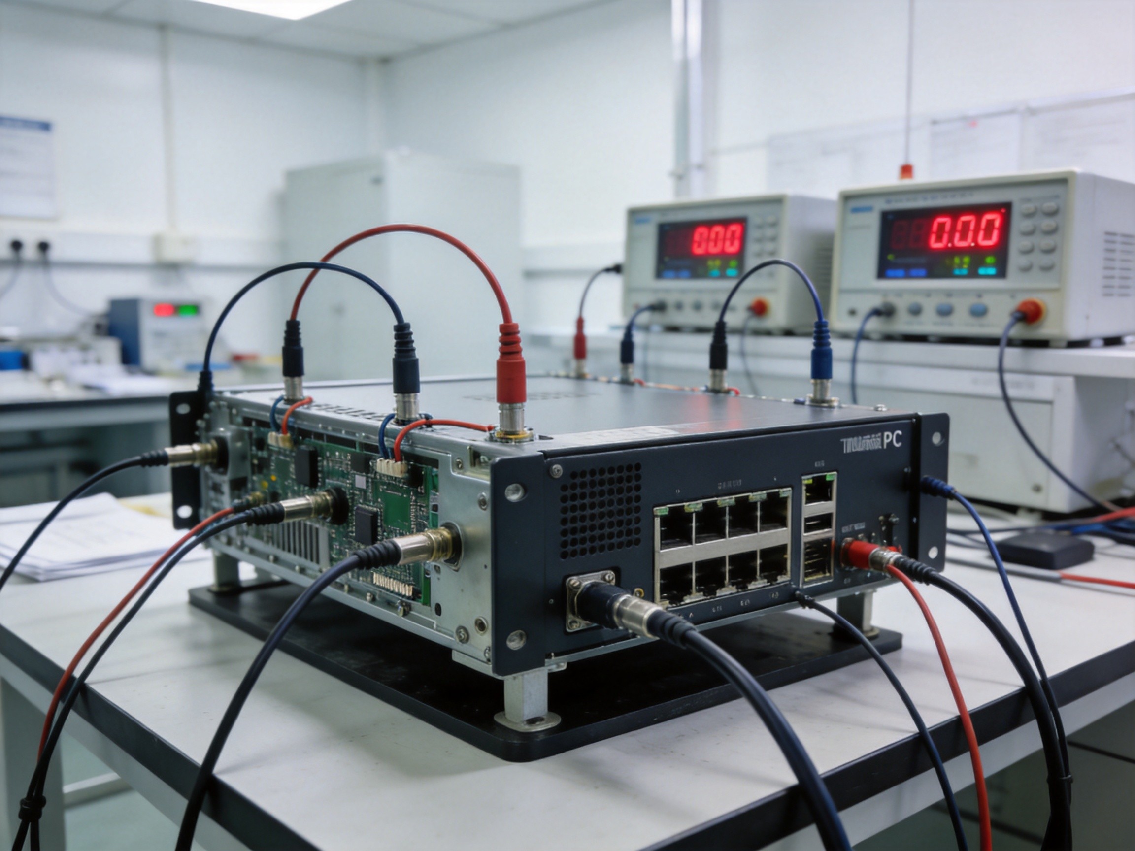
After heat has been conducted from the silicon die through the TIM, into the heat pipe, and out to the enclosure wall, the final step is transferring it to ambient air. External fin structures increase surface area for natural convection, but spacing, height, and orientation must be optimized for the expected mounting orientation. Fins too closely spaced trap boundary layer air and reduce efficiency. Fins too tall add weight and cost without proportional thermal benefit. The chassis material matters—aluminum extrudes easily into complex fin profiles but has lower conductivity than copper, while copper provides superior heat spreading but adds significant weight. The optimal design uses an aluminum chassis with a copper heat spreader plate bonded to the internal surface where heat pipes terminate. The external finish also affects performance: a matte black anodized surface radiates heat more effectively than bare metal, adding 5 to 10 percent to total heat dissipation in still-air conditions through radiation alone.
Thermal management in sealed industrial panel PCs is not a single component decision—it is a system-level engineering challenge spanning the entire thermal path from silicon to ambient air. Get any link in that chain wrong, and the entire system underperforms. Get it right, and the panel PC runs reliably for a decade without a fan, without a filter to clean, and without a thermal shutdown to explain to the production manager.