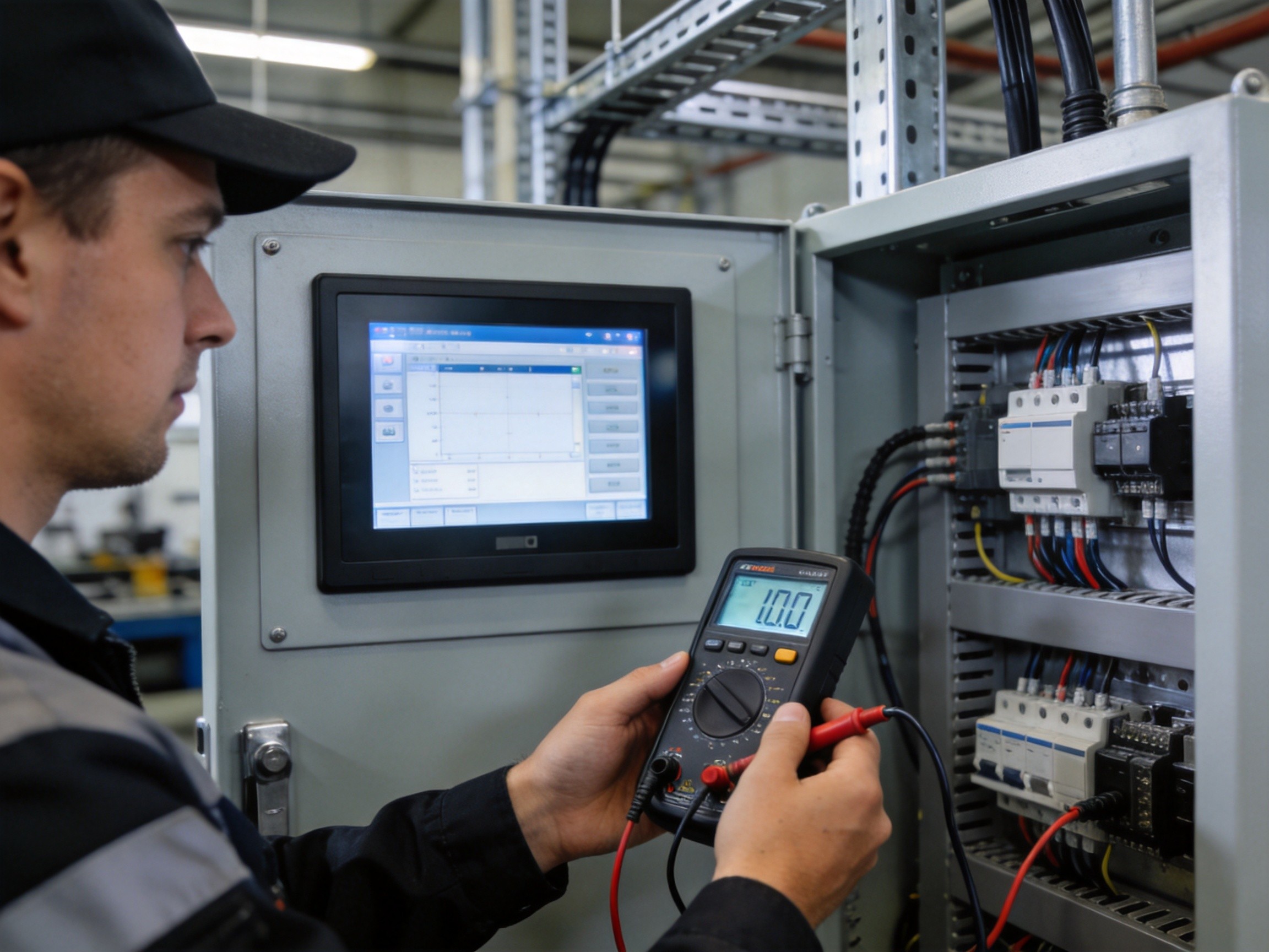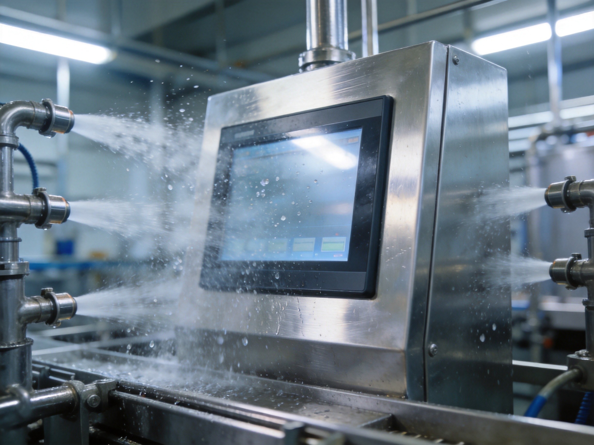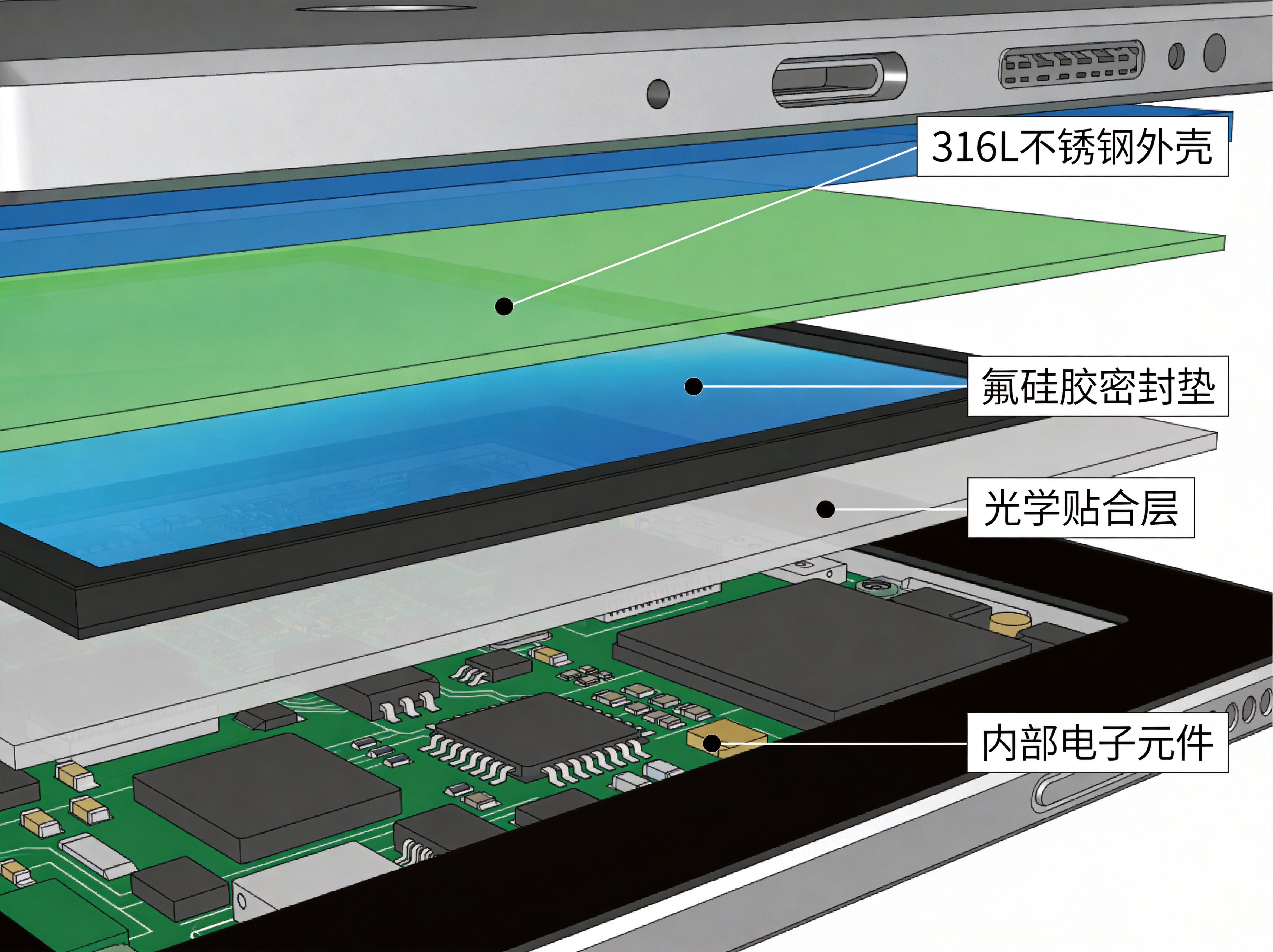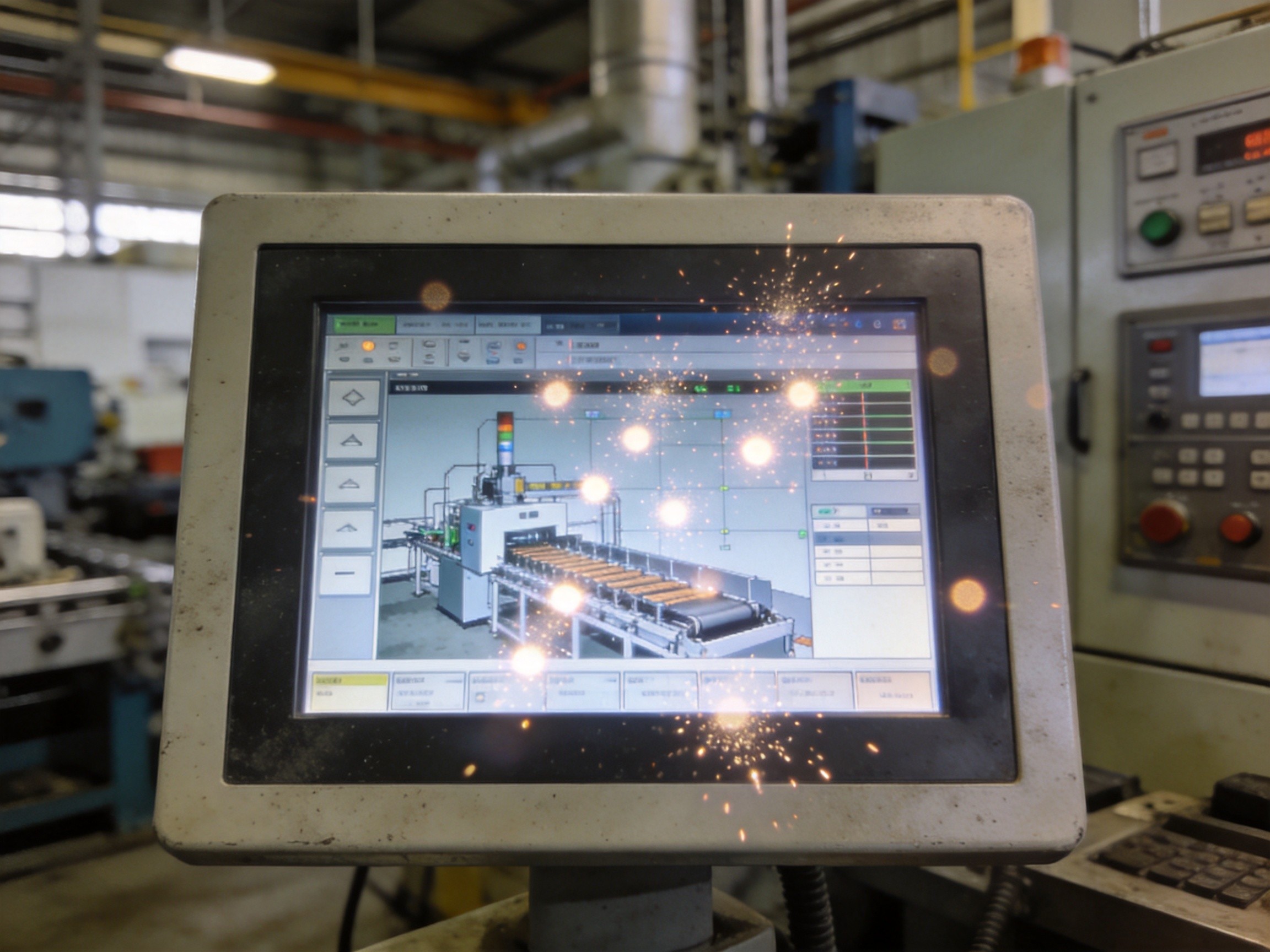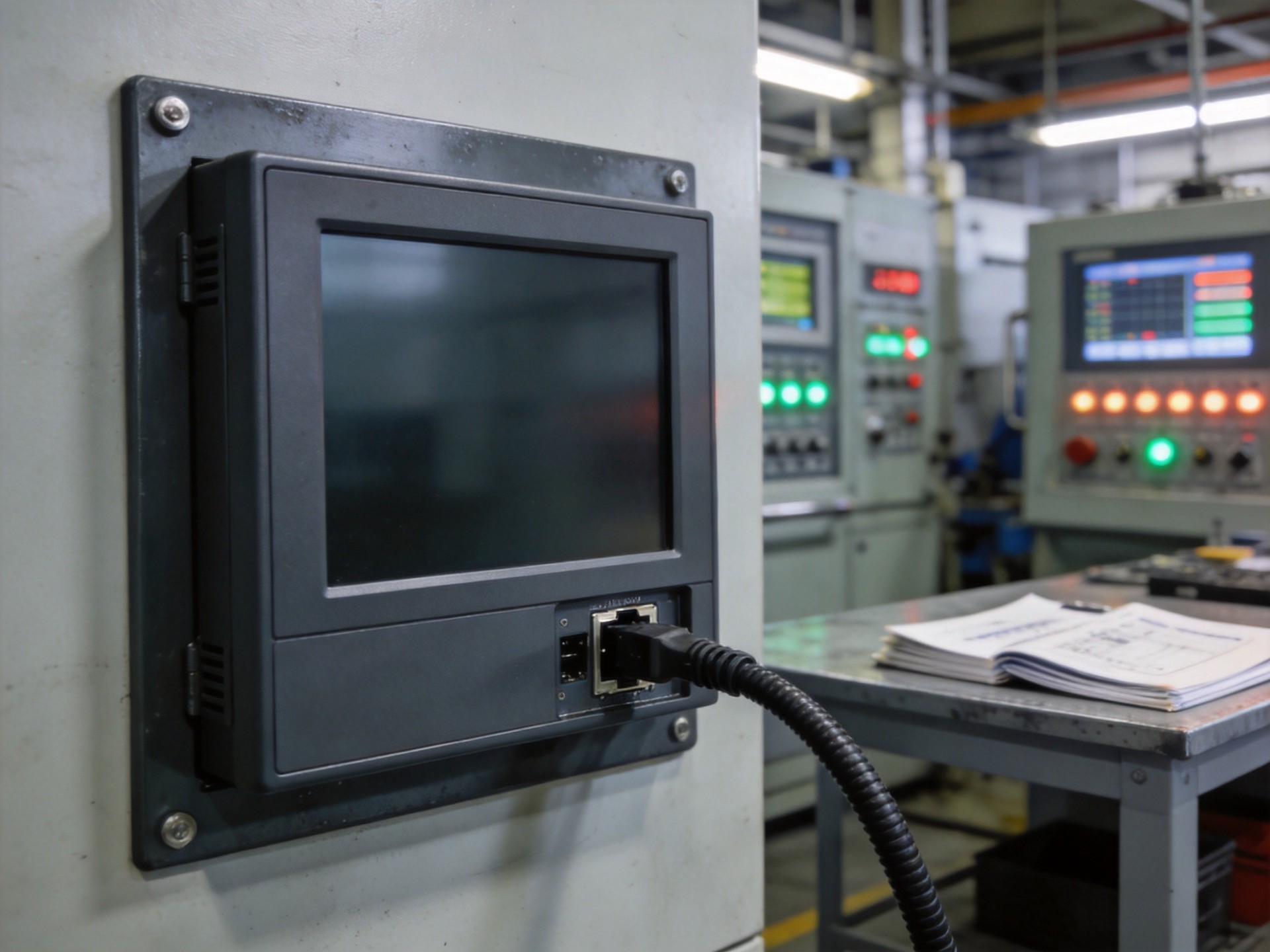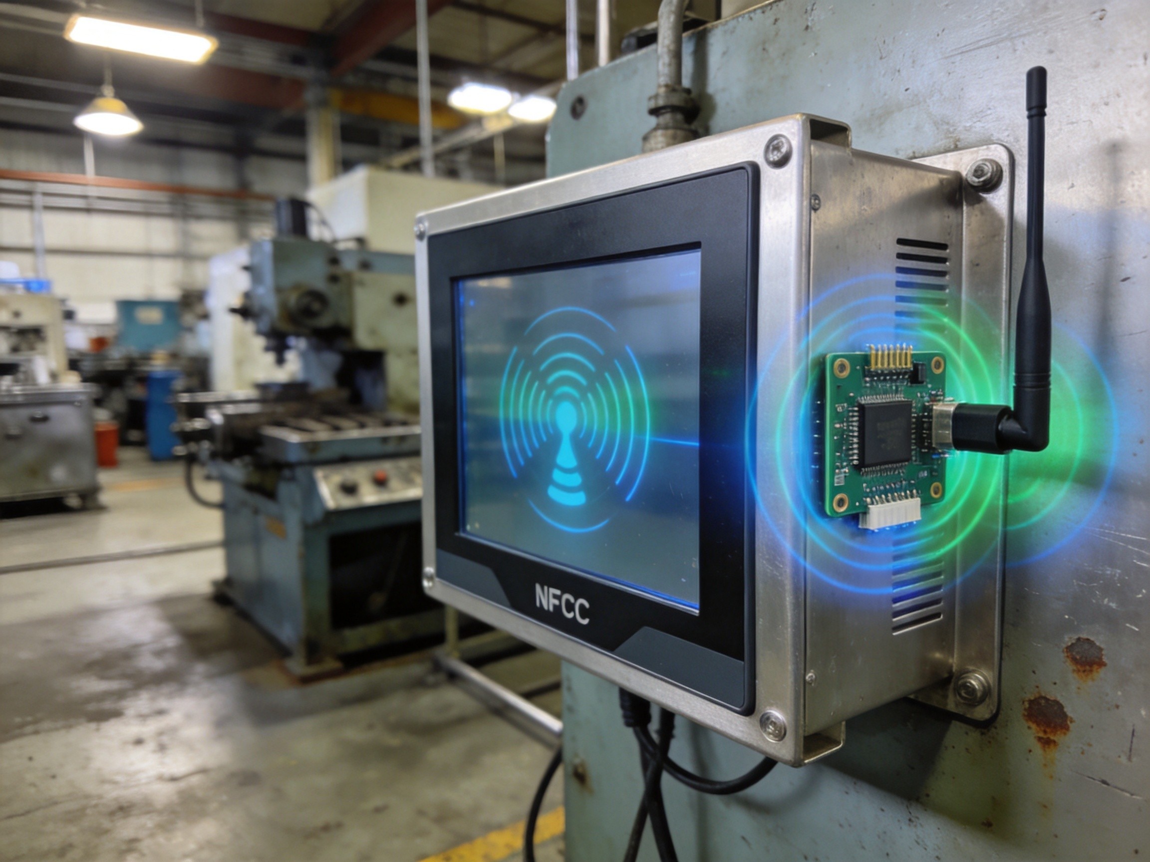
When deploying computing hardware in factory floors, outdoor kiosks, or dusty manufacturing cells, the first thing engineers look for is a fanless design. No moving parts means no dust ingress, no bearing wear, and no single-point mechanical failure. But removing the fan introduces a fundamental question: how do you extract 15 to 65 watts of thermal load from a sealed aluminum enclosure without active airflow? The answer lies in an intricate thermal architecture built on heat pipes, vapor chambers, and precision-engineered fin stacks. This article unpacks each layer of that architecture and explains why the whole is greater than the sum of its parts.
The Fundamental Challenge: Sealed Enclosure, Rising TDP
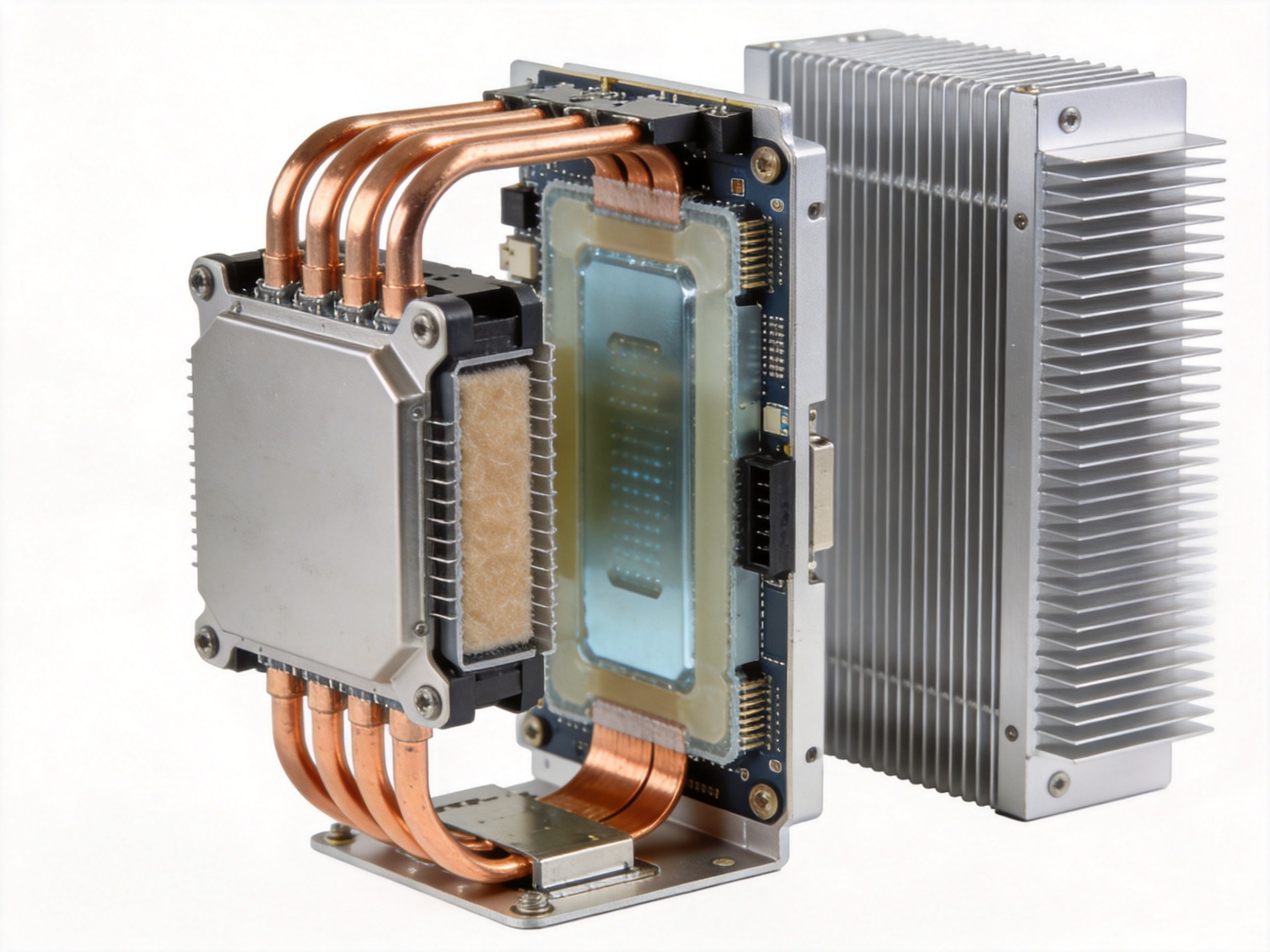
Modern embedded processors used in industrial edge computing easily push past 15W TDP under sustained load, with some configurations reaching 35W or higher. Inside a sealed chassis with IP65-rated gaskets, there is zero convective exchange with the outside air. Every watt must travel through solid materials: from the silicon die, across a thermal interface material, into a copper heat spreader, then into the heat pipe network, and finally to the external fin surface where natural convection and radiation take over. This thermal path is only as strong as its weakest link. A poorly machined contact surface or a marginally specified heat pipe can bottleneck the entire chain, throttling the CPU under workloads that the silicon itself could easily handle.
Heat Pipes: The Two-Phase Workhorse
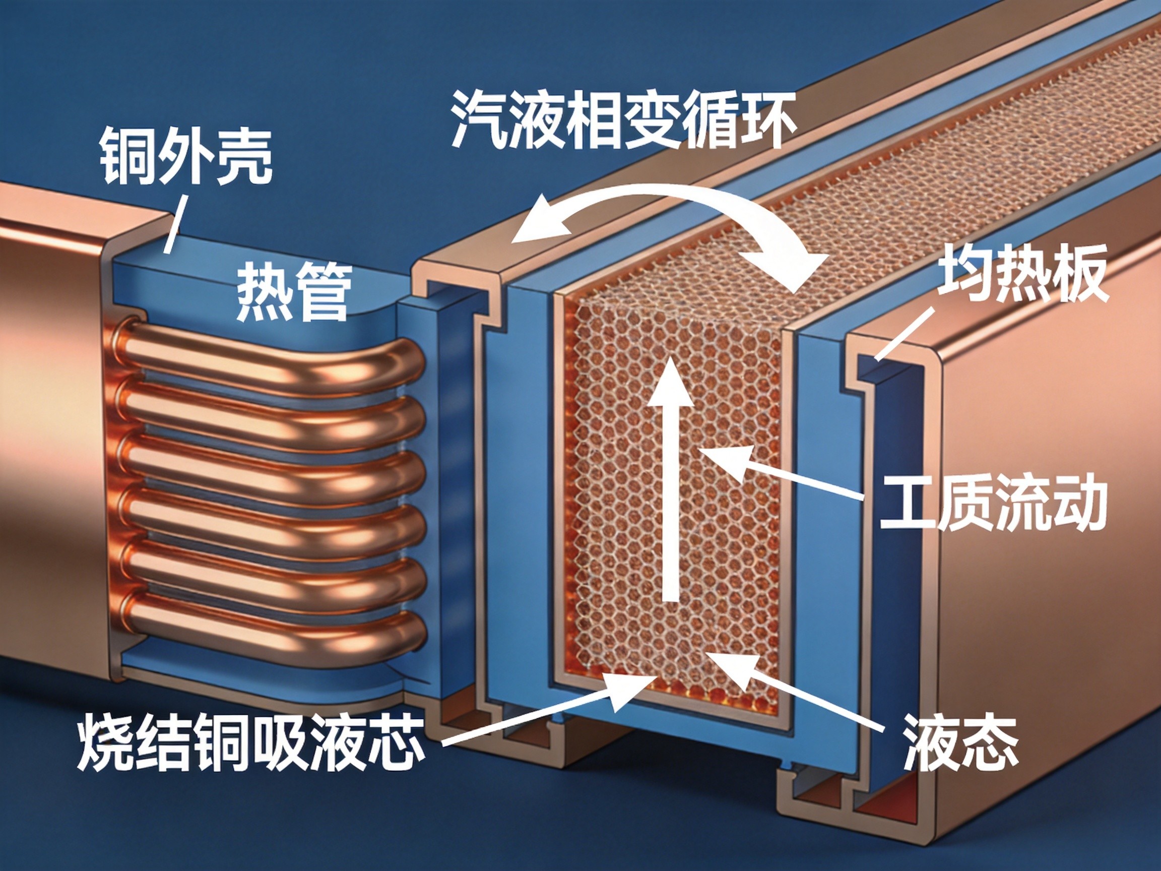
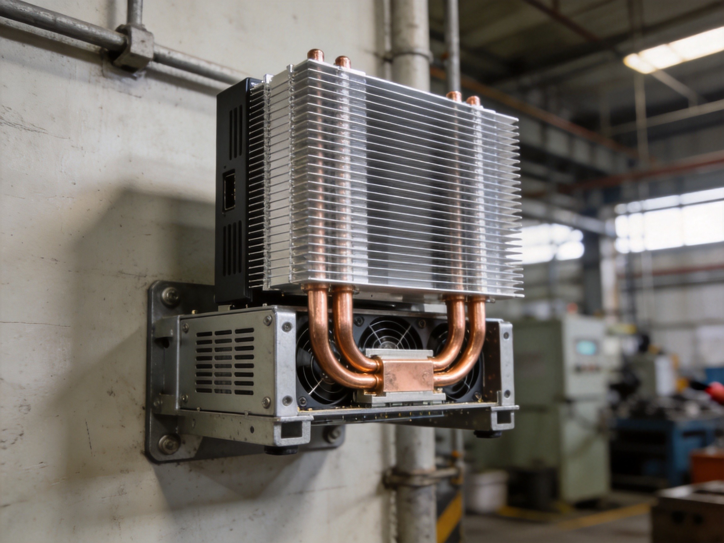
Heat pipes are the backbone of nearly every fanless industrial PC thermal design. A sealed copper tube contains a small amount of working fluid — typically distilled water under partial vacuum. When the evaporator end absorbs heat from the processor, the fluid vaporizes and travels to the cooler condenser end, where it releases latent heat and condenses back into liquid. A sintered copper wick lining the inner wall draws the liquid back to the evaporator via capillary action. This closed-loop cycle achieves effective thermal conductivity in the range of 5,000 to 20,000 W/m·K, dwarfing solid copper at roughly 400 W/m·K. The key design parameters are pipe diameter, bend radius, and orientation. In compact mini-PC enclosures, heat pipes are often flattened and routed through tight bends, which can reduce their power-carrying capacity if not carefully modeled during the mechanical design phase.
Vapor Chambers: Spreading Heat in Two Dimensions
When heat flux density exceeds what a discrete heat pipe can efficiently capture, vapor chambers enter the picture. A vapor chamber is essentially a flattened, planar heat pipe — a sealed copper envelope with an internal wick structure and working fluid, but designed to spread heat across its entire XY plane rather than transporting it along a single axis. They excel in scenarios where the processor die is small relative to the available cold plate area, creating a high heat flux “hot spot.” By spreading the thermal load laterally before it enters the heat pipe network, vapor chambers can reduce junction-to-case thermal resistance by 30 to 50 percent compared to a solid copper base plate of equivalent thickness. This makes them particularly valuable in fanless designs that use low-profile enclosures, where Z-height constraints limit the thickness of the thermal stack.
Fin Stack Design: The Final Exchange Interface
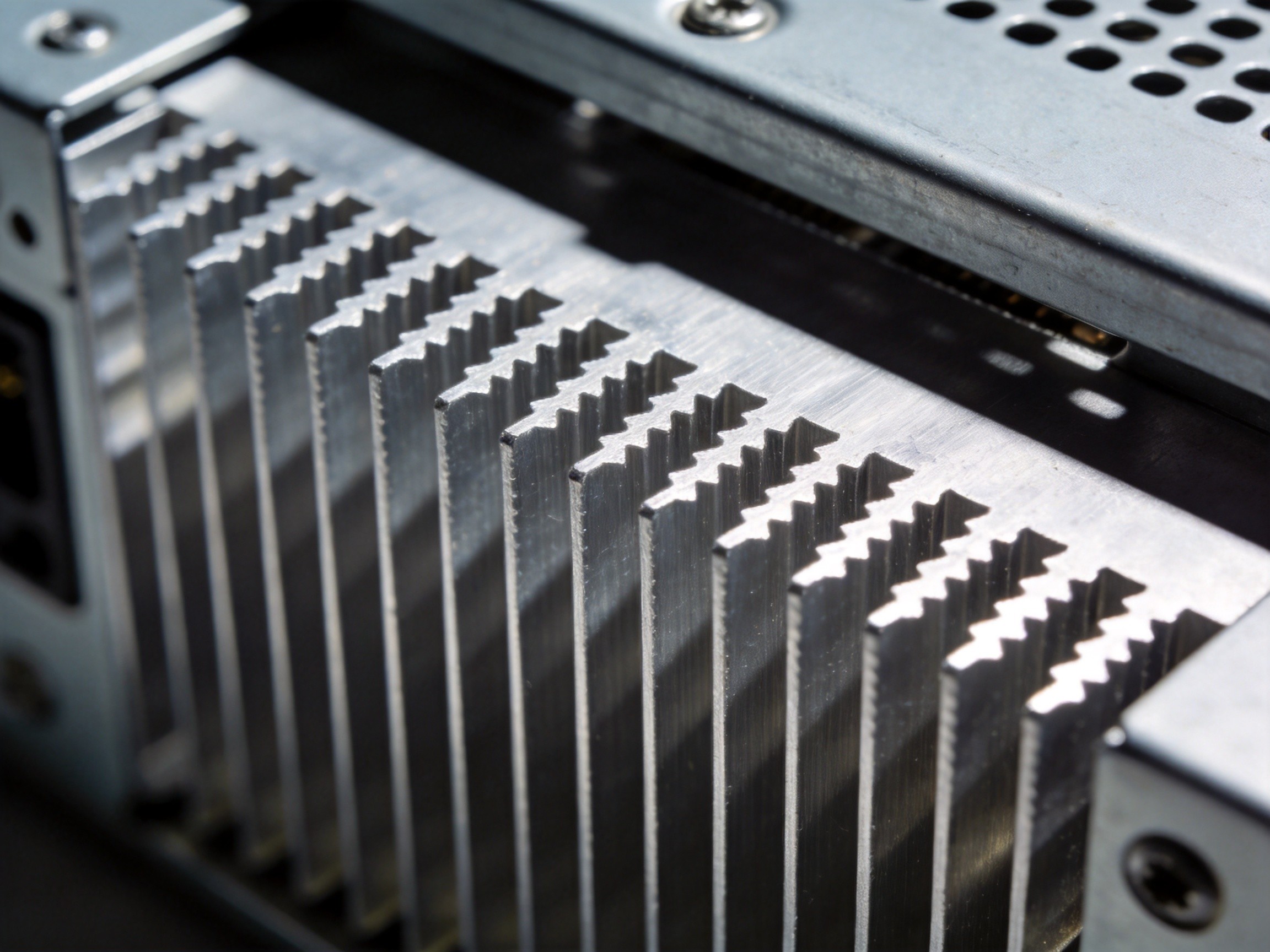
Once heat reaches the external surface of the chassis, the fin stack becomes the critical last mile. Natural convection cooling is driven by the temperature difference between the fin surface and ambient air, but the geometry matters enormously. Fin pitch, thickness, and height must be balanced: too dense a fin array traps stagnant air between fins, while too sparse a design wastes valuable surface area. For vertical mounting orientations — the optimal configuration for natural convection — fin channels should run vertically to encourage chimney-effect airflow. Some designs incorporate serrated or interrupted fin profiles to trip the boundary layer and improve heat transfer coefficients. The thermal performance of a well-designed fin stack can rival small forced-air solutions, making fanless industrial PCs not just a dust-proof alternative but a genuinely high-performance thermal platform. Brands like KOXIAN have refined these geometries across multiple product generations, achieving reliable thermal headroom for sustained workloads in ambient temperatures up to 50°C.
Thermal architecture in fanless industrial PCs is a systems-level discipline. Heat pipes, vapor chambers, and fin stacks are not independent components — they form a continuous thermal chain where each link must be sized, shaped, and positioned to complement the others. For engineers specifying edge computing hardware, understanding this chain is the difference between a box that works on paper and one that survives years of 24/7 operation inside a sealed roadside cabinet. As processor TDPs continue to rise with each new silicon generation, the sophistication of passive cooling design will only grow in importance. The integration expertise demonstrated by companies like KOXIAN in this domain reflects a broader industry trend: thermal management is no longer a supporting function — it is a core differentiator.