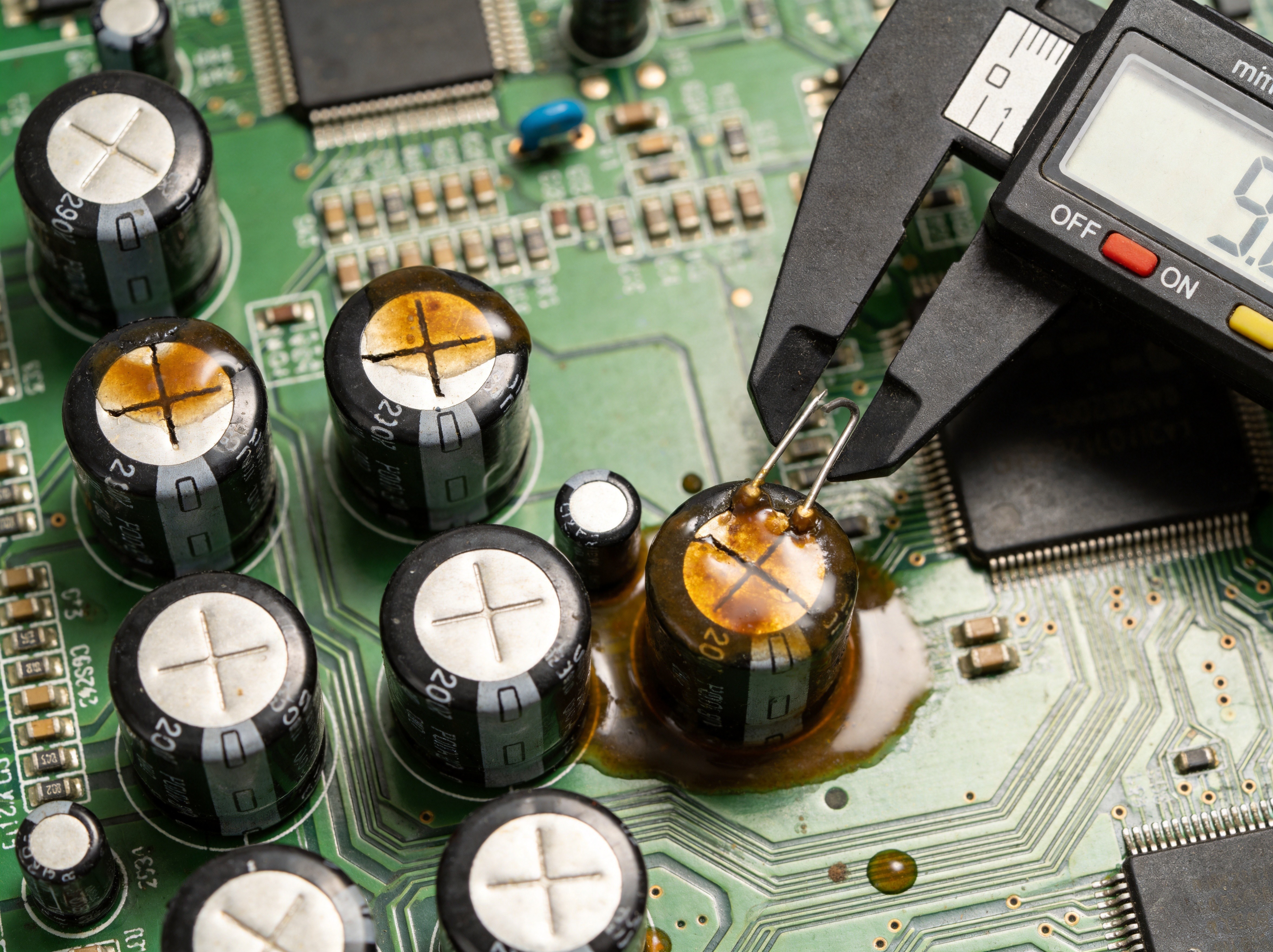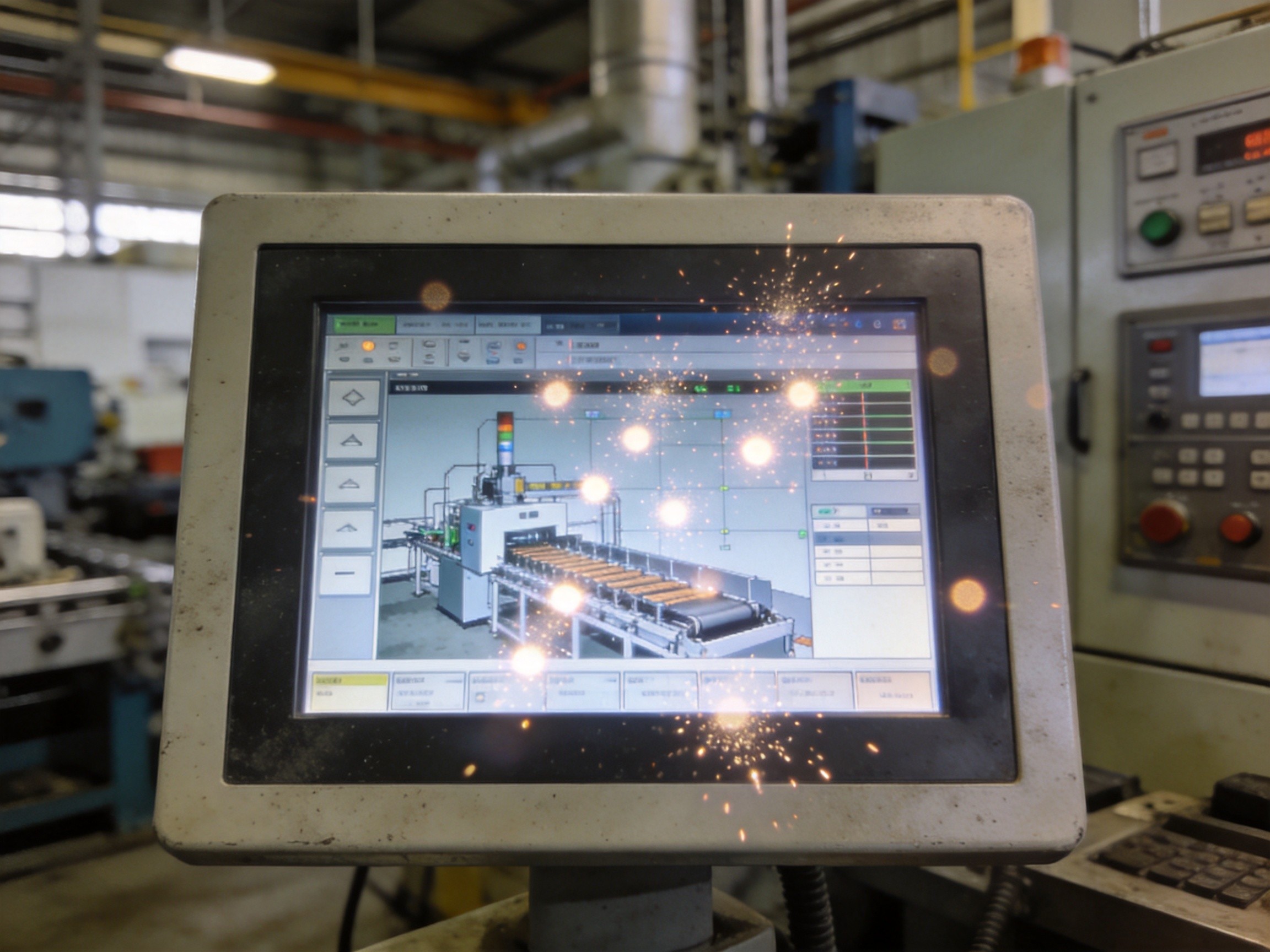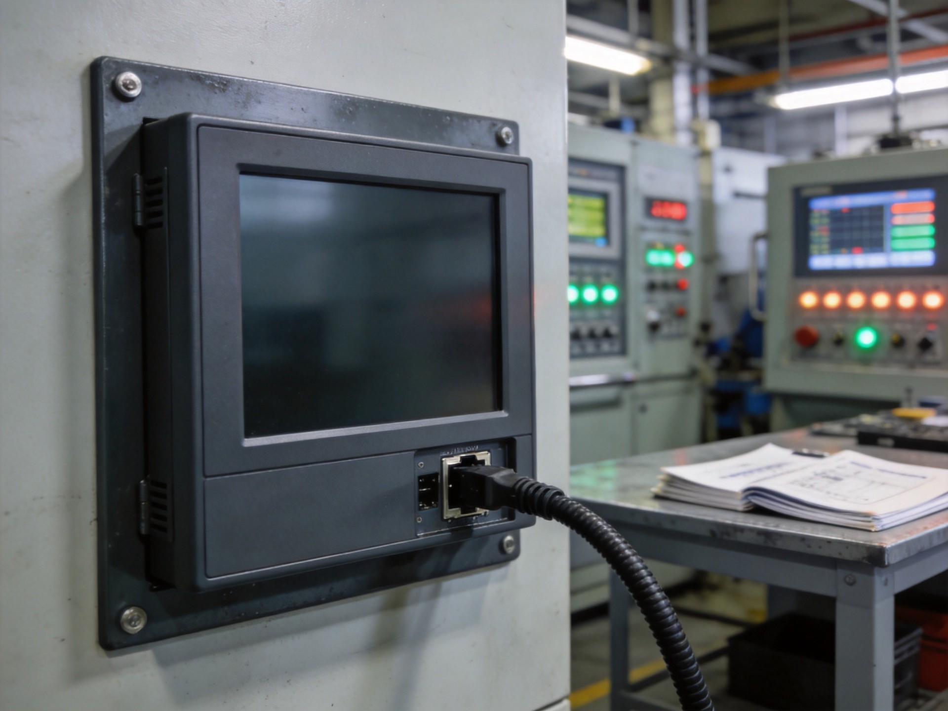
Power surges and transient overvoltage events destroy more industrial computing hardware than any other single failure mechanism. Warranty-return analysis shows 30 to 40 percent of mainboard failures trace to the power input stage. The root cause is rarely a single lightning strike but the cumulative effect of smaller transients—motor startups, utility switching, arc welding equipment, and inductive kickback from solenoids and relay coils. Each event damages a semiconductor junction or degrades a capacitor dielectric. The component eventually fails, appearing random when it was predictable and preventable.
The Three-Layer Protection Architecture
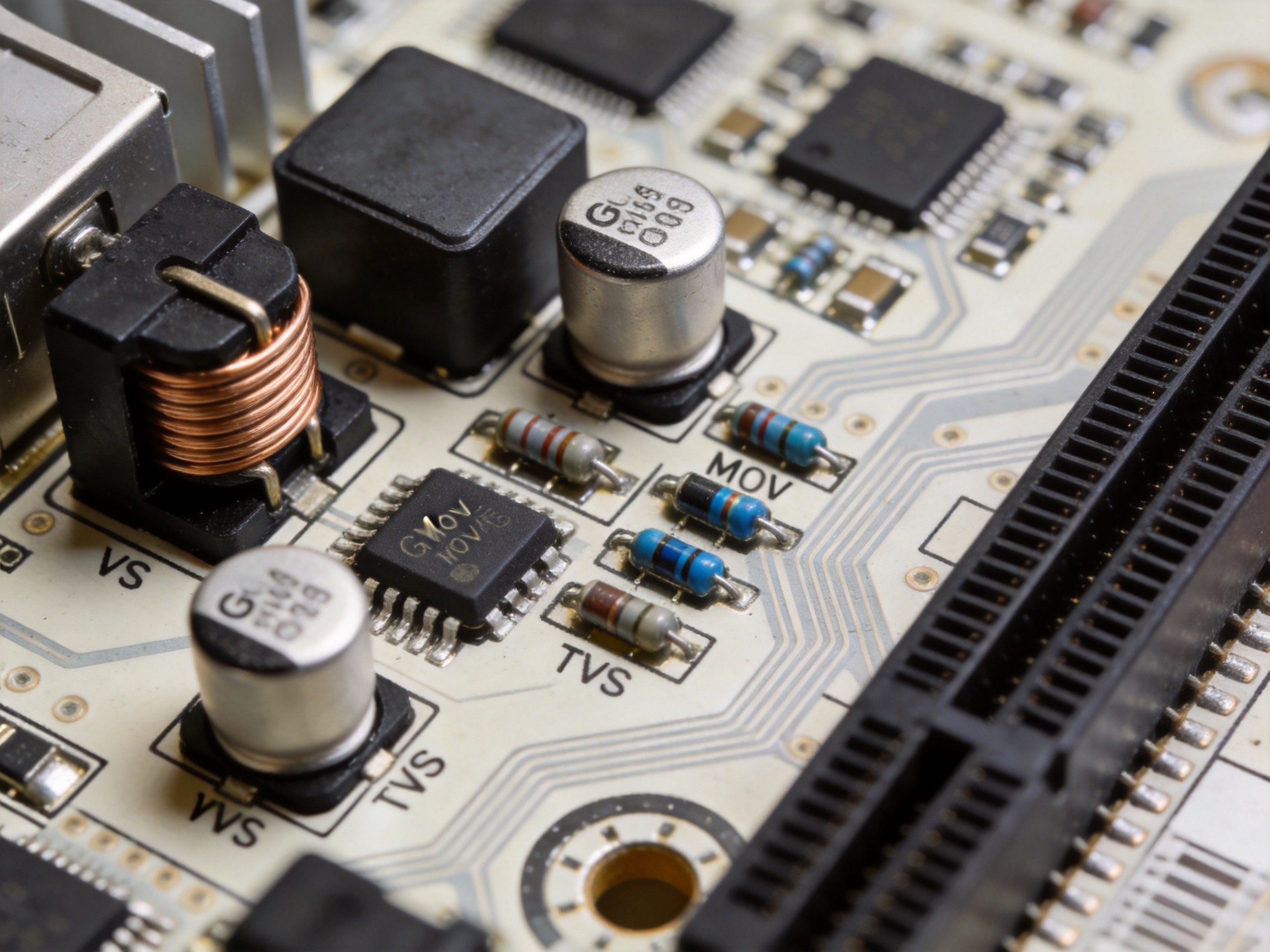
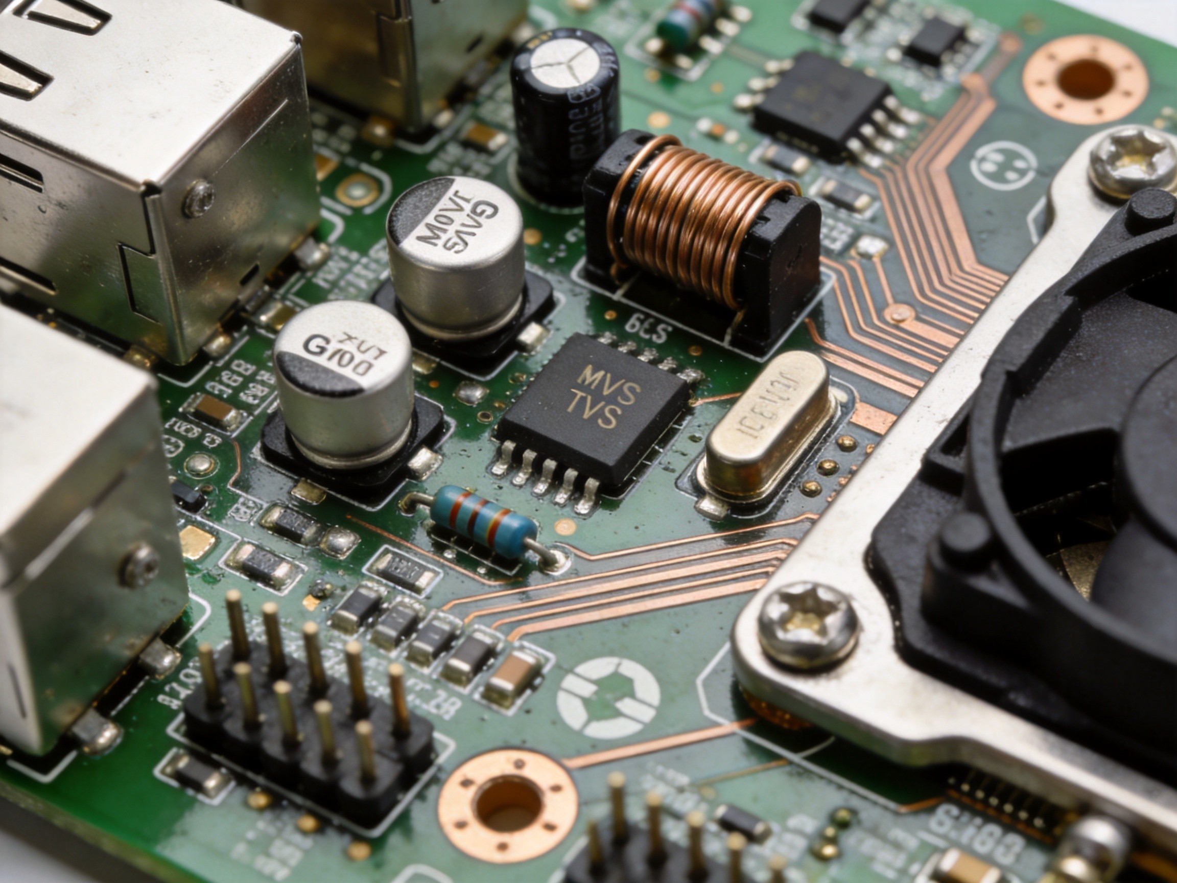
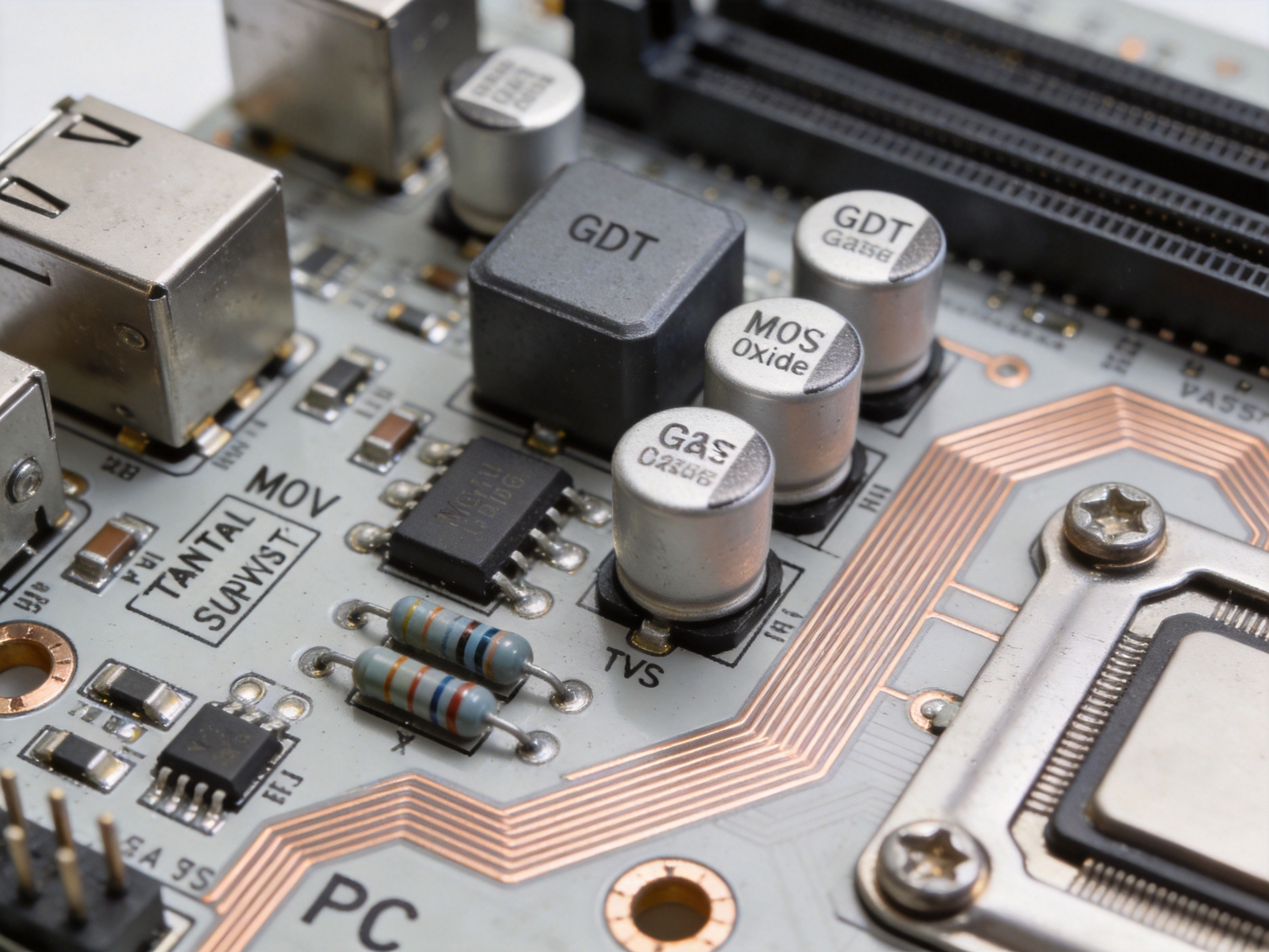
A robust protection circuit uses a staged defense, each layer optimized for a different transient category. The first line is a gas discharge tube at the power input, shunting kilovolt-level transients to chassis ground within microseconds. GDTs handle the high-energy events that would vaporize solid-state components. The second layer is a metal oxide varistor clamping voltage to a safe level. MOVs are fast, inexpensive, and effective, but they degrade with each surge event—a fact often overlooked in maintenance schedules. The third layer is a transient voltage suppression diode array at the voltage regulator input pins. TVS diodes respond in picoseconds and clamp with precision. KOXIAN mainboard designs implement this three-layer architecture with careful PCB layout: trace length between protection components and the protected IC must be minimized, because even a few centimeters of copper adds enough inductance to delay the clamping response.
Common-Mode vs Differential-Mode Transients
A critical distinction is between common-mode and differential-mode transients. A differential-mode surge appears between the positive and negative power rails—the classic motor startup current spike on the same DC bus. Common-mode transients appear between the power rails and earth ground, typically from capacitive coupling in long cable runs or ground potential differences across a facility. Many protection circuits address differential-mode surges adequately but leave common-mode paths unprotected. The result is a ground-loop current flowing through the mainboard’s ground plane, creating voltage gradients that confuse logic-level signals and can latch up sensitive CMOS circuits. The fix is a common-mode choke combined with a Y-class capacitor network providing a controlled path for common-mode energy to chassis ground. This component costs less than two dollars and prevents failures that cost thousands in downtime.
Wide-Input Voltage Design as a Protective Strategy
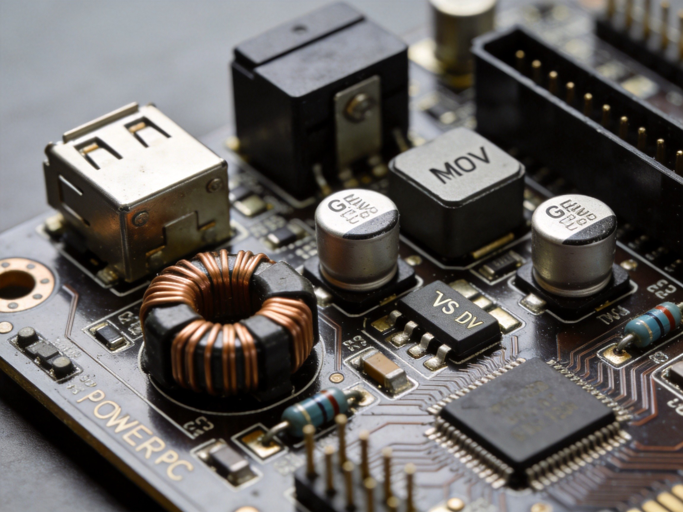
An effective surge protection strategy is designing the power input stage for a wide voltage range—typically 9 to 36 volts DC. A wide-input design means the voltage regulator can absorb a transient that pushes the nominal 24-volt bus to 32 or 34 volts without passing the overvoltage to downstream electronics. The input capacitors and inductors filtering the DC supply also act as low-pass filters for high-frequency transient energy before it reaches the switching regulator. This is complemented by reverse-polarity protection using a P-channel MOSFET, eliminating the forward voltage drop of a simple series diode. KOXIAN Panel PCs incorporate a 9-36V wide-input design with reverse-polarity, overvoltage, and undervoltage lockout protection integrated into a single front-end module tested to withstand IEC 61000-4-5 surge waveforms at Level 4 severity.
Field Verification and Preventive Maintenance
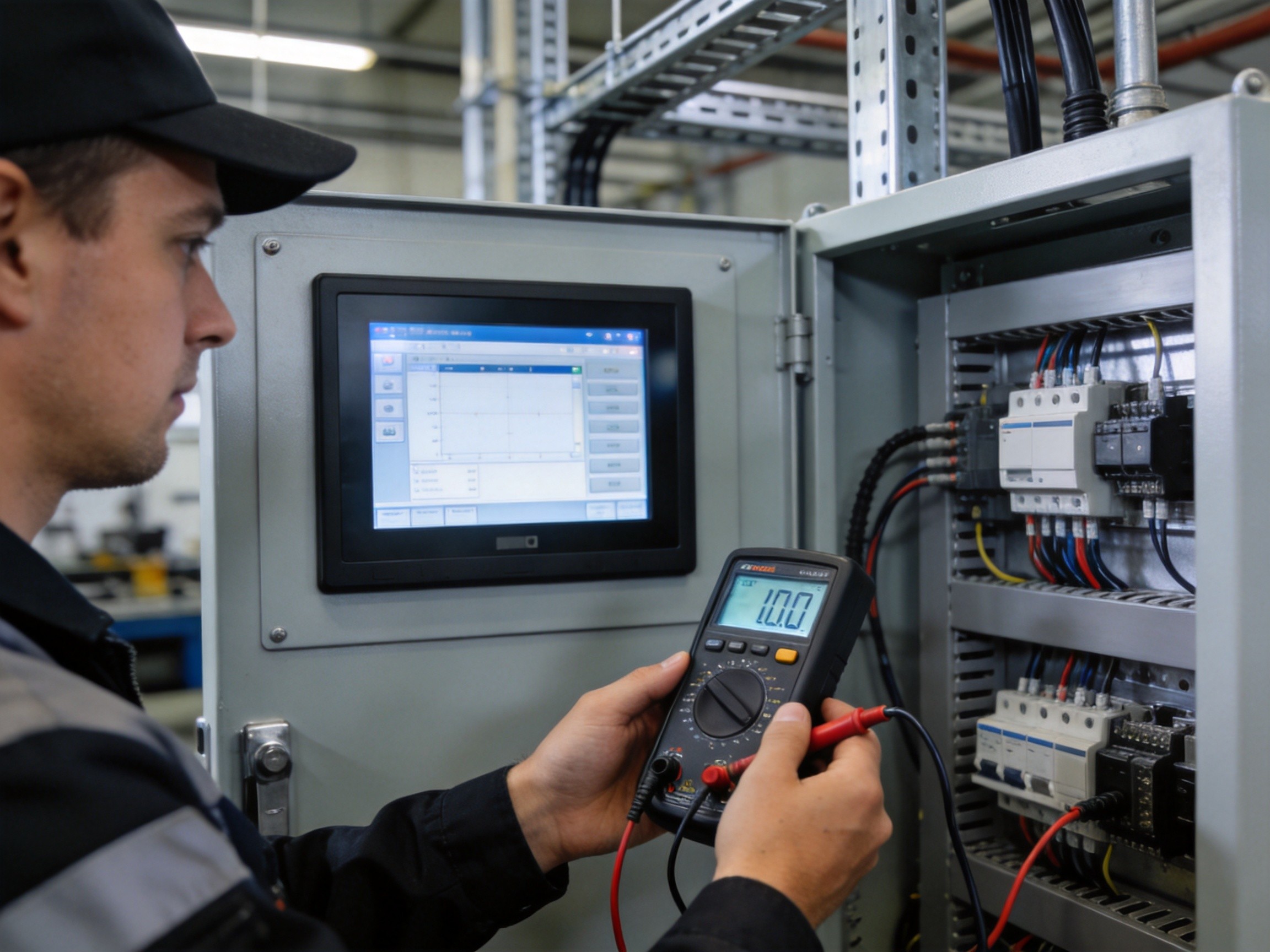
The best protection circuit degrades over time, invisibly, until a surge passes through to the mainboard. MOVs are the main culprit: each surge event raises leakage current until they fail short or open. Preventive maintenance should include annual testing of protection components to verify clamping voltage remains within specification. Where taking equipment offline is impractical, an inline surge protection module provides a field-replaceable sacrificial element. The maintenance cost is trivial compared to an unplanned production stop. The industry has the engineering knowledge to build surge-immune industrial computing hardware. The gap is in the discipline of specifying, installing, and maintaining protection circuits as rigorously as the computing hardware they protect.
Power surge damage is one of the most preventable failure modes in industrial computing. What separates installations that run for years from those that fail every few months is not technology access but the willingness to treat surge protection as a first-class design requirement. For industrial PC mainboards, that means a three-layer protection cascade, common-mode filtering, wide-input design, and a maintenance schedule that verifies the protection is still working. Every dollar spent on protection circuits saves orders of magnitude more in avoided downtime and lost production.