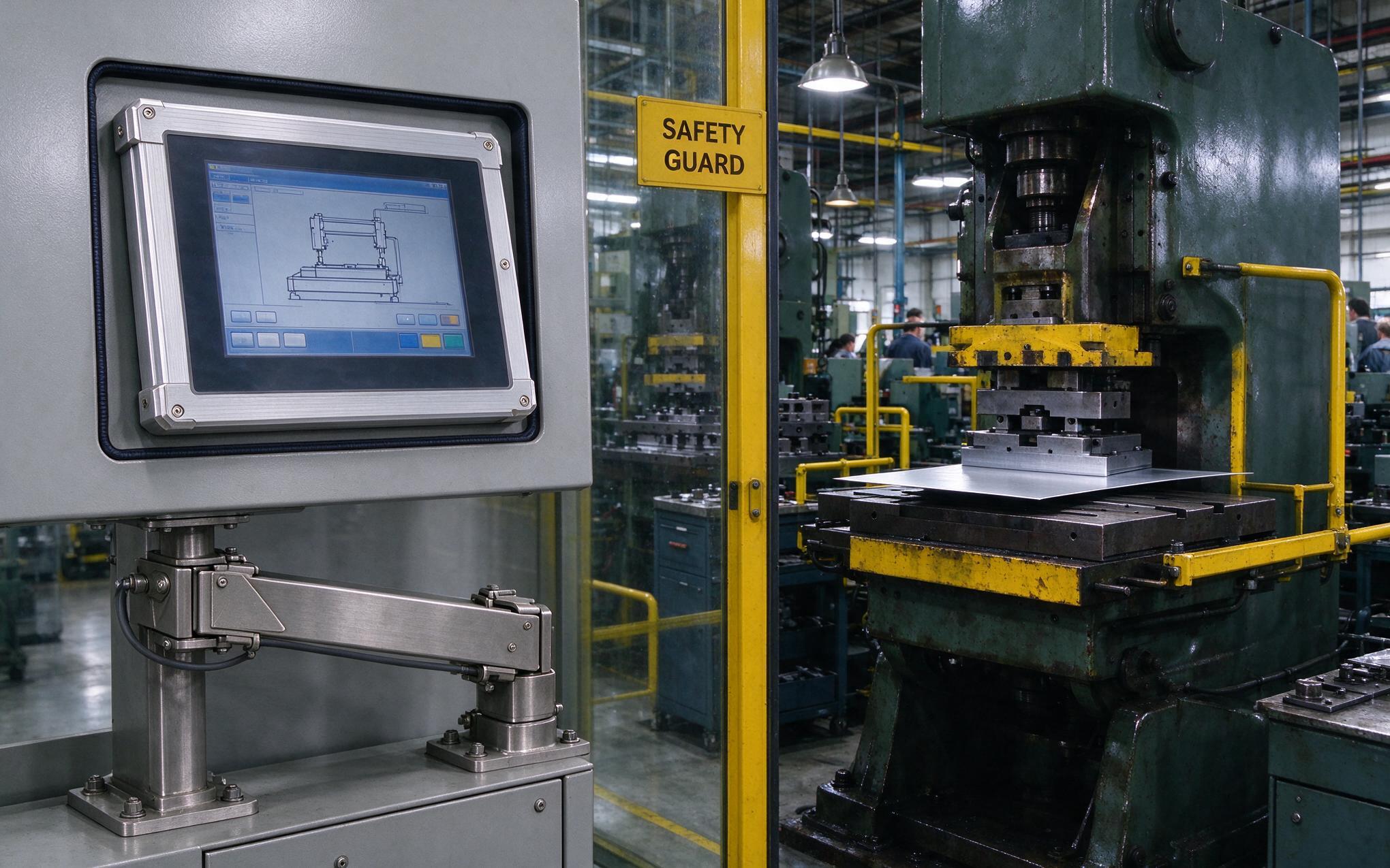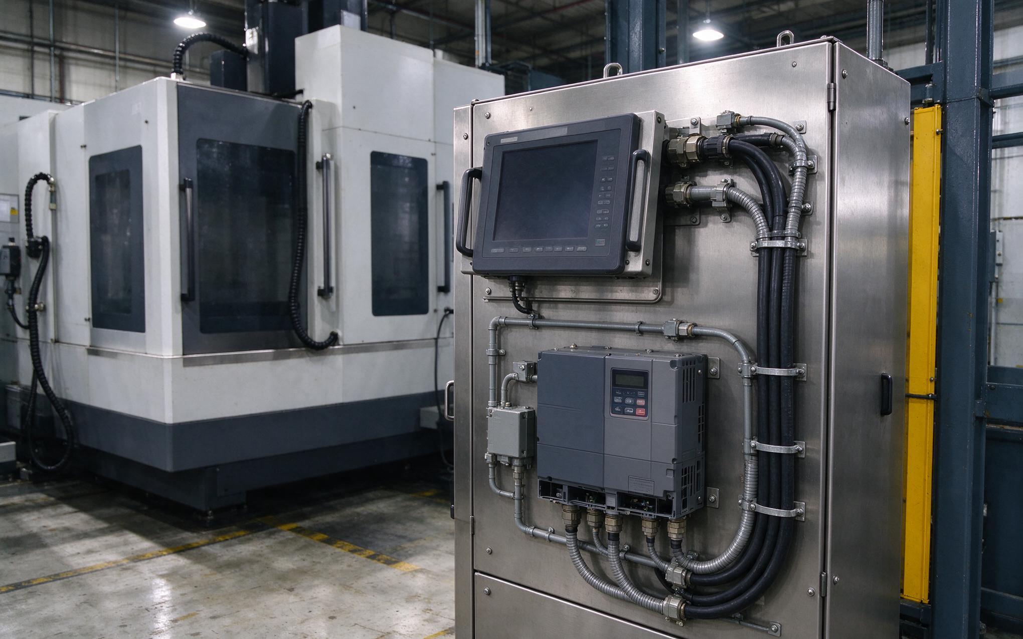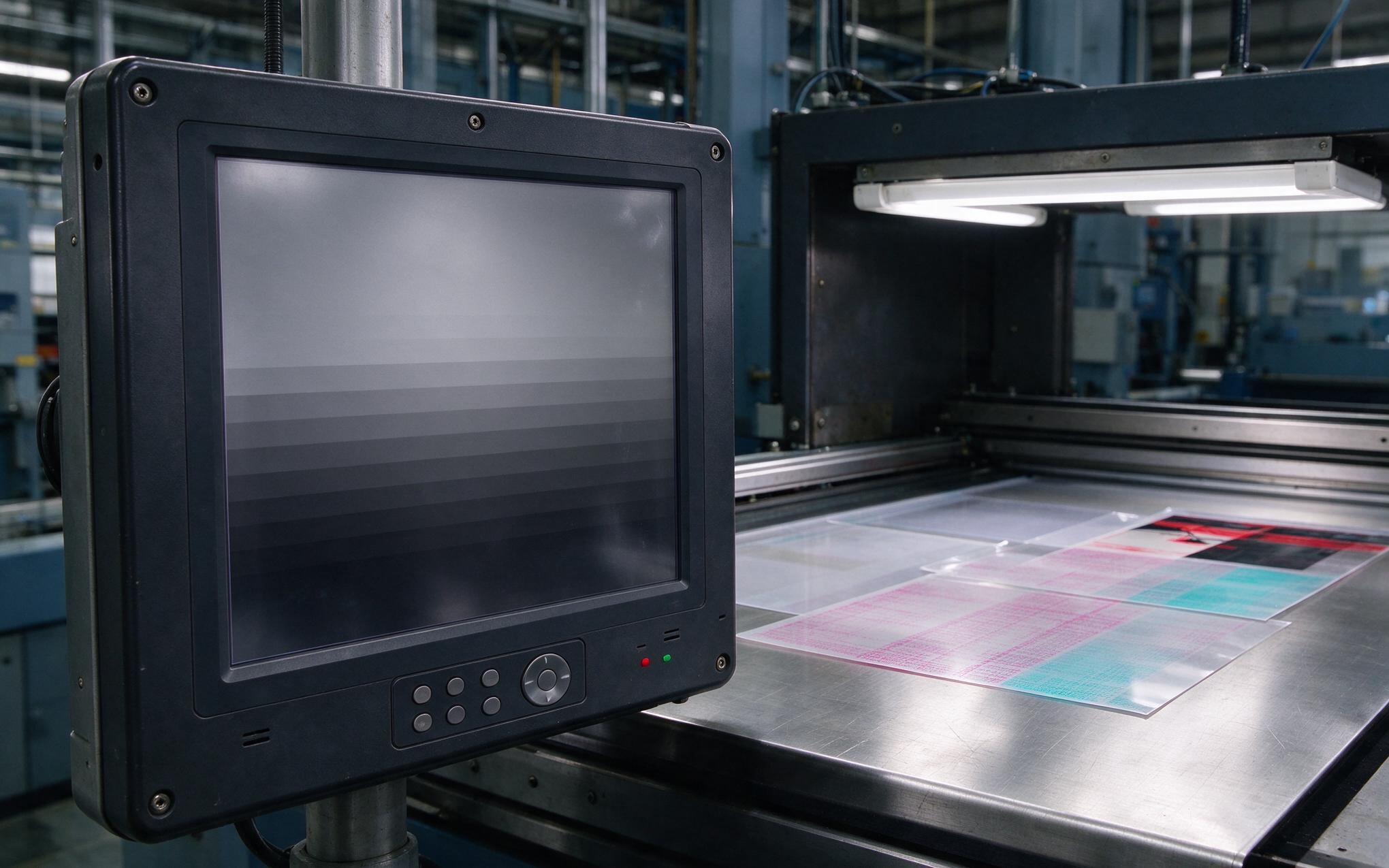
Maintenance technicians tracing intermittent screen resets on a machining line notice a consistent pattern: nearly every event lands seconds after the adjacent variable-frequency drive accelerates a spindle. The industrial display monitors on that line share tray space and panel cutouts with motor circuits, yet the units were selected on brightness and sealing alone. Pulse-width-modulated drives broadcast broadband energy from their switching frequency well into the megahertz range, and that energy arrives through every path a cabinet offers. A reset tied to spindle speed, rather than temperature or running hours, points at electromagnetic coupling, not computing load. The weakest bonded gap in the shield chain is usually the source.
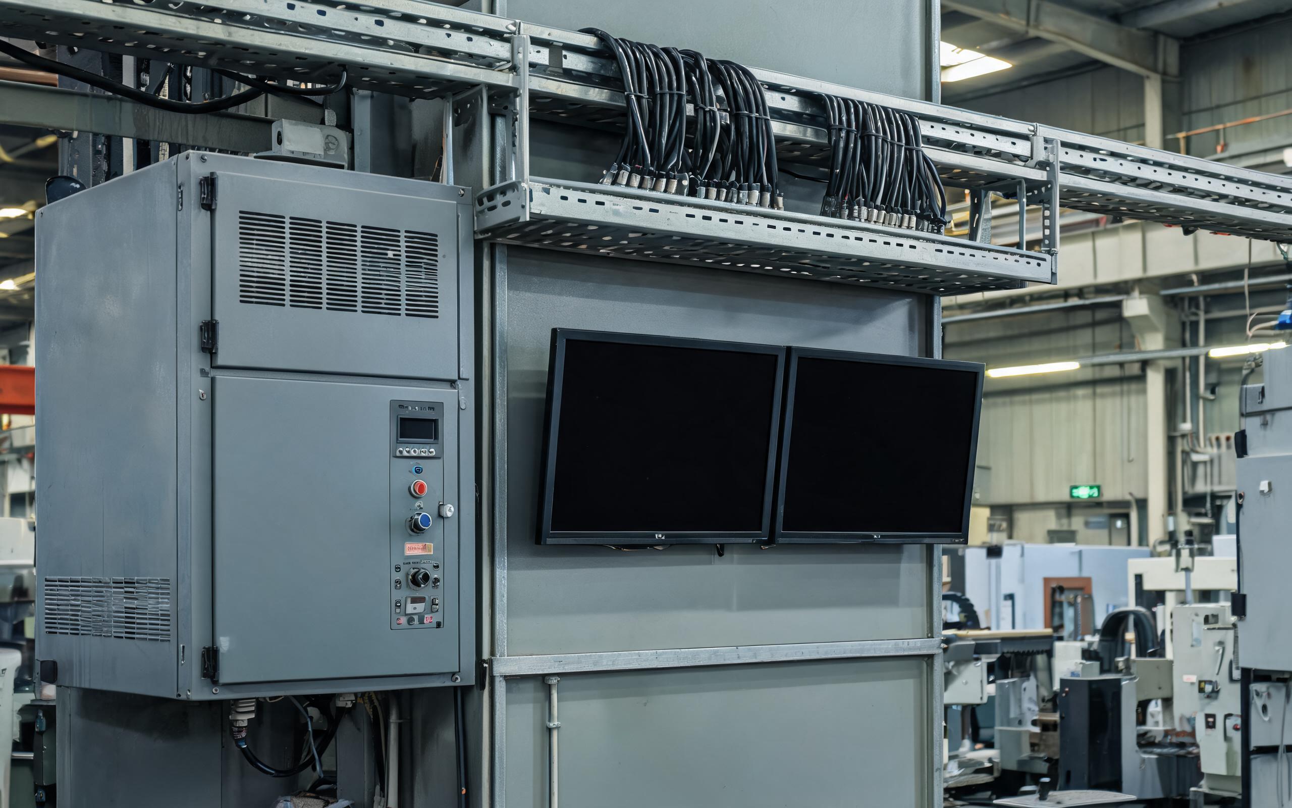
EMI Coupling Paths into Panel-Mounted Industrial Display Monitors
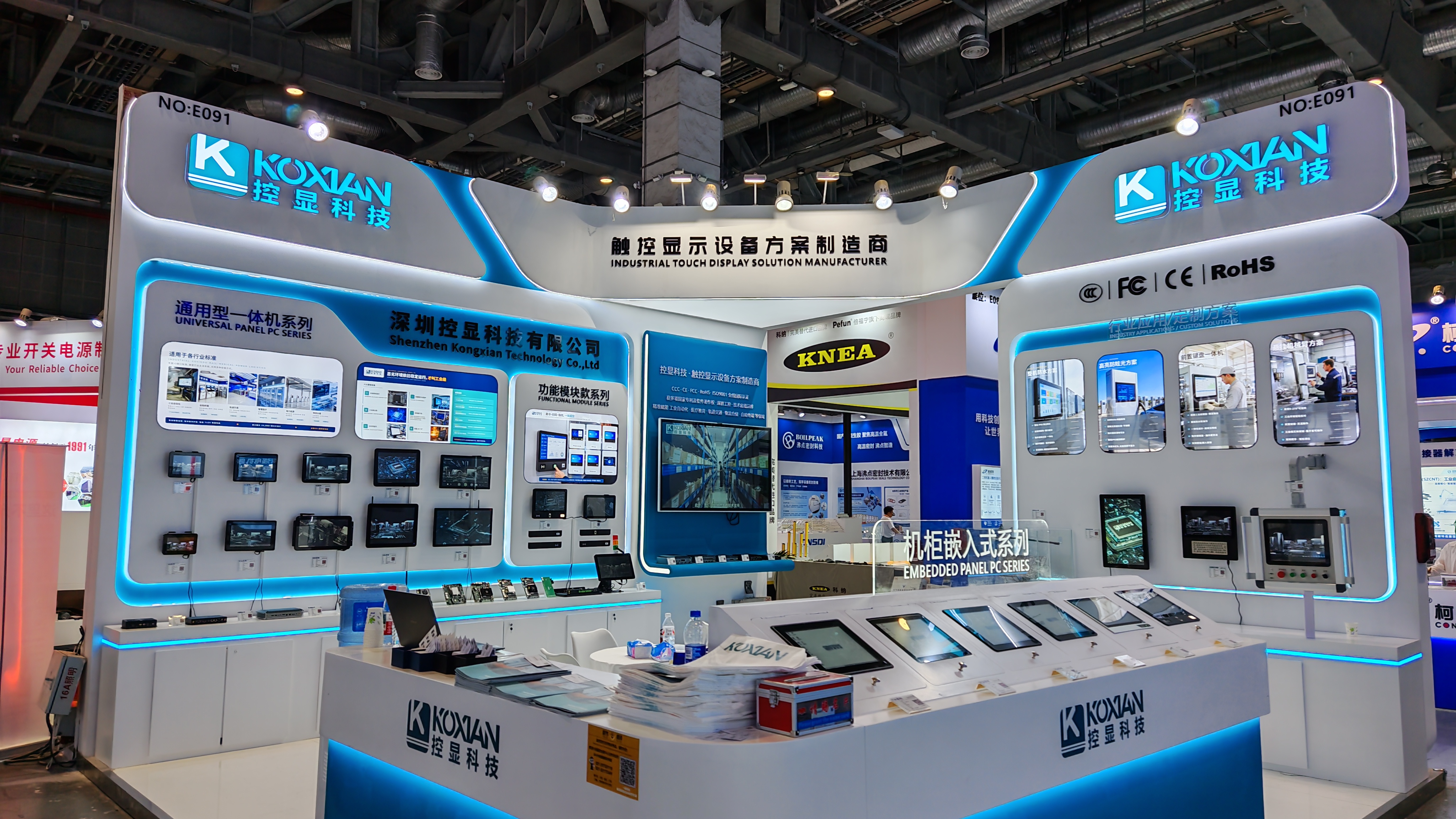
A drive floor does not attack industrial display monitors through one route. Pulse-width modulation launches conducted noise back onto the shared feeder and radiated noise off motor cable, which becomes an antenna once its length approaches a quarter wavelength. Enclosure manufacturers, including KOXIAN, identify three dominant openings: the cutout gap, the cable gland plate, and the seam where the rear box meets the bezel. A narrow slot radiates as effectively as a deliberate aperture, and a painted meter-long flange can leak more than a louvered vent. Every crossing wire is a second front, carrying common-mode current past the seal. An industrial panel mount display with a strong IP rating still fails when those openings and conductors are addressed separately.

Bonding Enclosure Panels into One Low-Impedance RF Surface
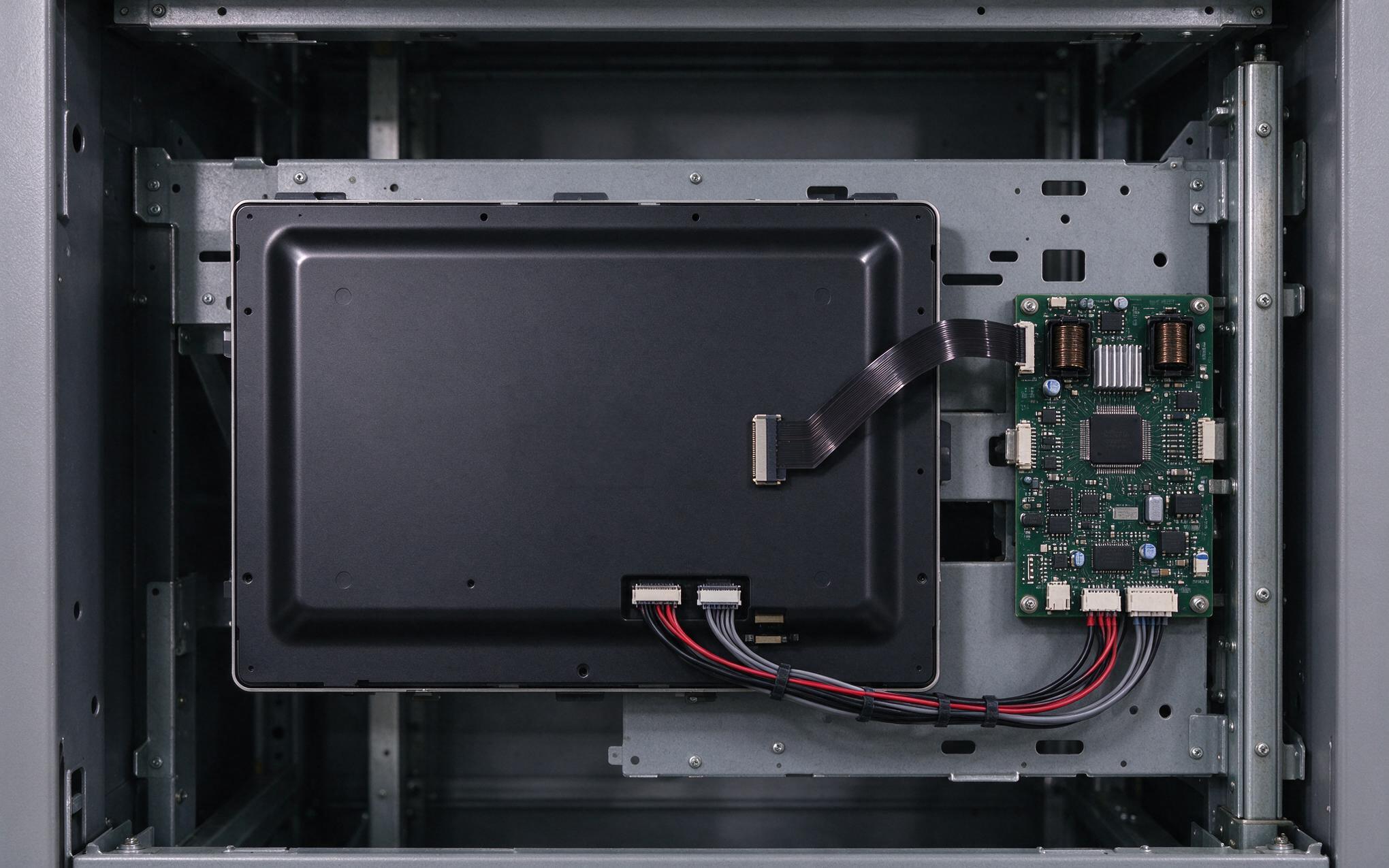
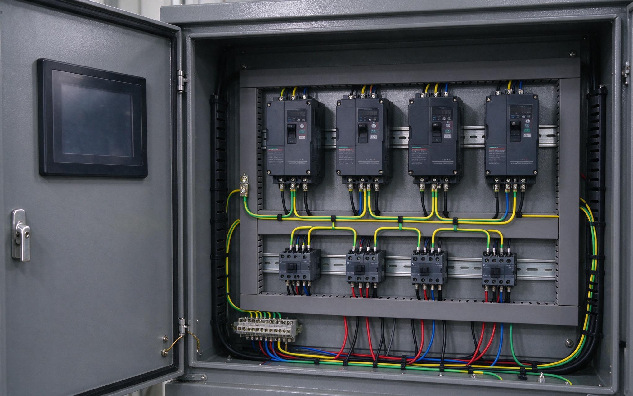
At direct current a single equipment grounding conductor looks continuous, but at megahertz noise follows a different rule. Inductive reactance rises with frequency, and a short braid already presents impedance at the fastest fast-transient edges. The practical answer is RF bonding: every panel, gland plate, door, and mounting stud joins one conductive surface through many short, unpainted contacts. Paint is masked or removed at each fastener, serrated washers bite through conversion coatings, and tight seams receive conductive elastomer gaskets. Panel mounting becomes part of the shield because the cutout flange bonds industrial display monitors to the cabinet door, extending the conductive surface. Construction of a rugged industrial monitor treats contact density as a measurable quantity, similar to the cast flange and gasket land geometry used in the KOXIAN K2 series.
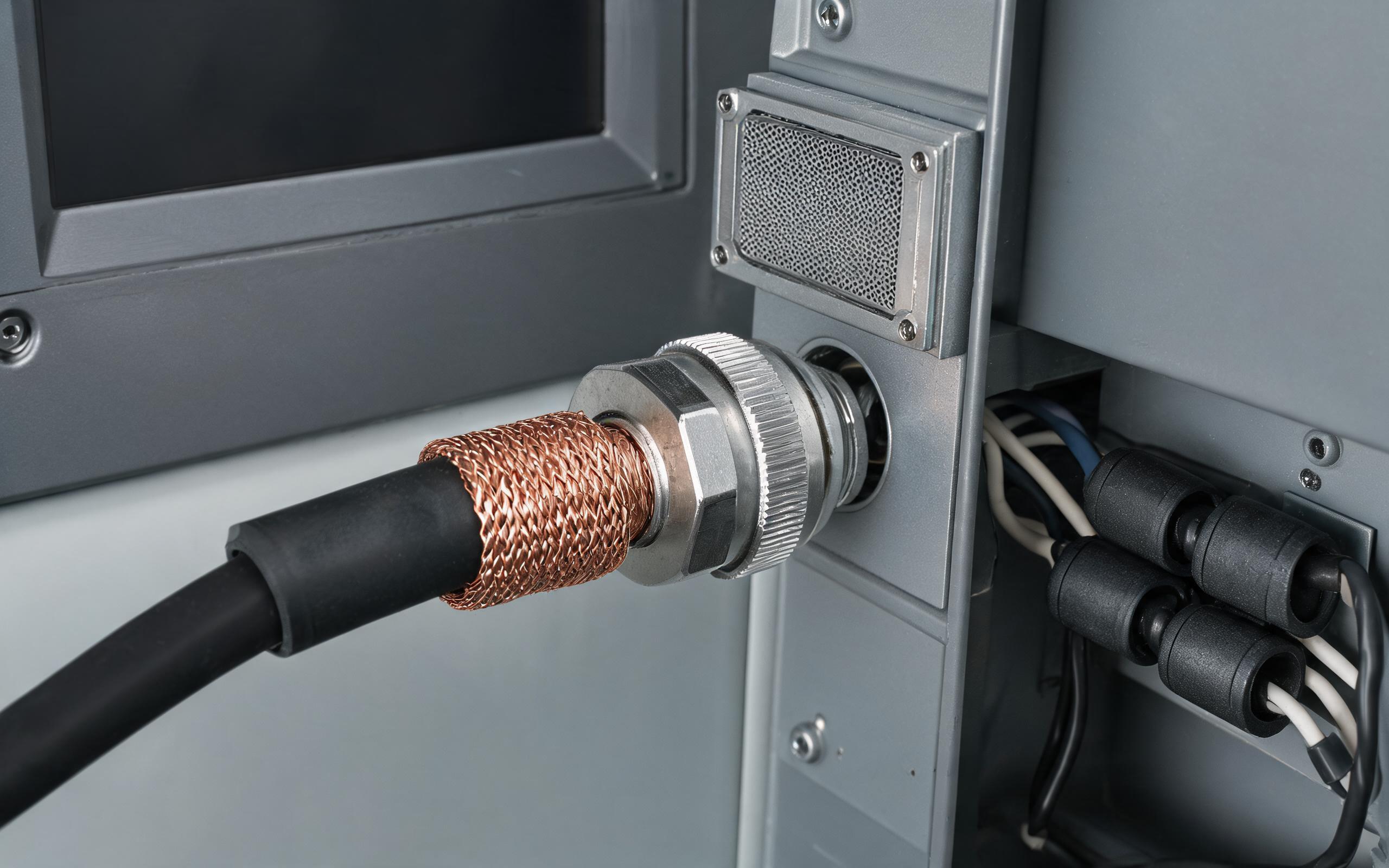
Cable Shield Termination, I/O Filters, and Tray Segregation
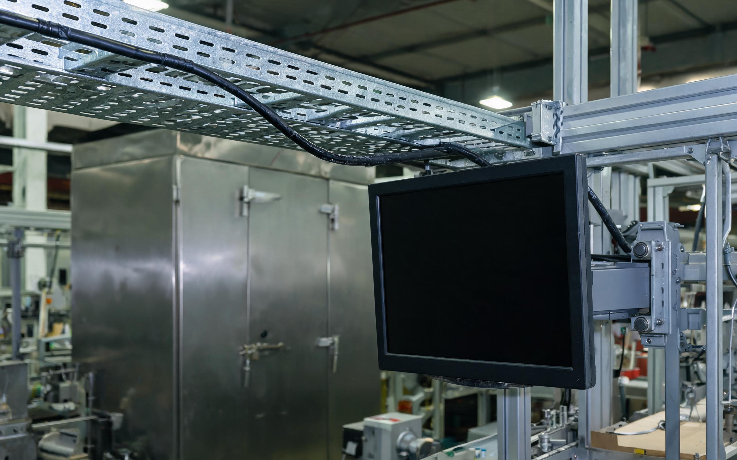
A bonded enclosure only protects what crosses its boundary correctly. A drain wire tailed to a single screw becomes a radiating stub; the correct termination is full 360-degree contact at a conductive cable gland or metallic connector shell. Feed-through capacitors and panel-mounted filters belong on that same boundary, oriented so no unfiltered wire loops back inside. Clamp-on ferrites on the internal harness add common-mode attenuation for residual energy on network and serial lines. On the tray, motor runs keep twenty centimeters of separation from signal cables and cross at ninety degrees. Commissioning checklists for industrial display monitors now list shield contact resistance alongside torque values, because cable plant can feed the very apertures the chassis was bonded to close.
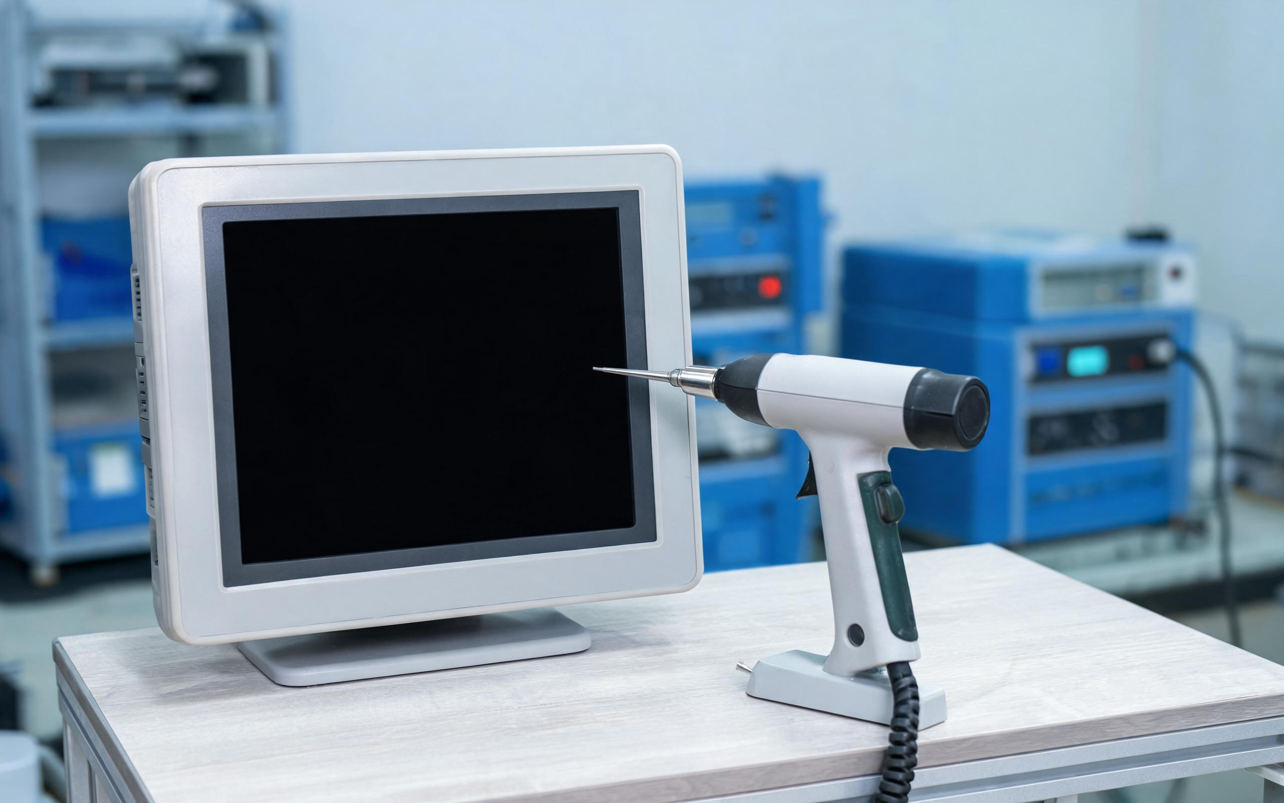
Verification Against IEC 61000-4 Immunity Sequences
Field observations from drive-dense stamping shops show that machines built on the KOXIAN bonded-enclosure layout hold display function through immunity sequences that reset panels assembled with painted seams. The relevant standards divide the environment into repeatable tests. IEC 61000-4-2 applies electrostatic discharge to accessible points, IEC 61000-4-4 injects fast transients on supply and signal terminals, and IEC 61000-4-5 applies slower surge events. The radiated and conducted immunity sections expose the unit to field levels representative of a drive aisle, and performance criteria define whether temporary degradation passes or fails. A passing prototype means little unless production units repeat the steps, so every batch of industrial display monitors audits torque, paint masking, and gasket compression on the line rather than assuming them from a drawing.
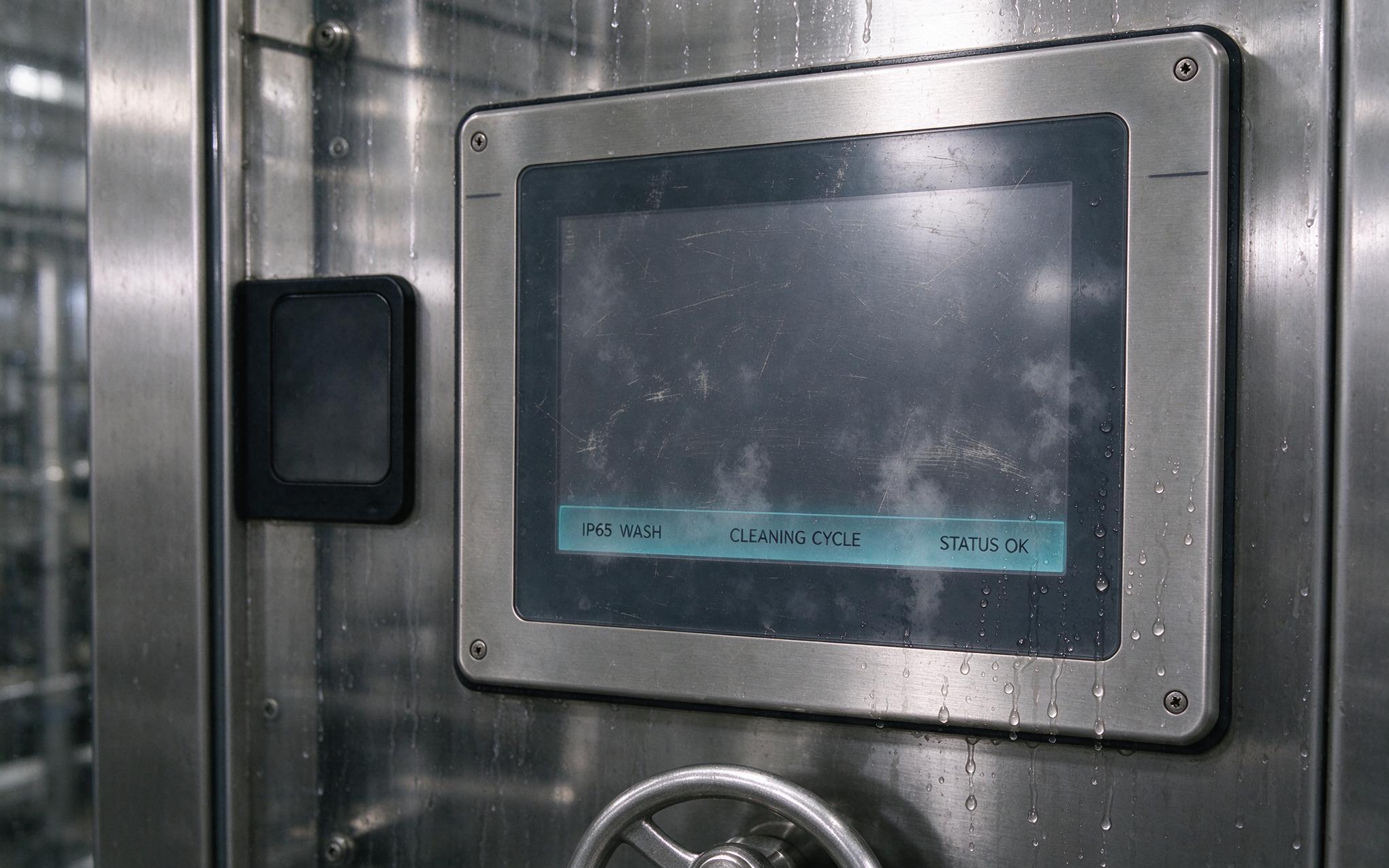
Reset and freeze events blamed on weak computers are usually shield-chain failures wearing a software costume. The fix is architectural: bond every panel and door into one RF surface, terminate shields around their full circumference, place filters at the boundary, and prove the result with the same IEC 61000-4 waveforms the floor produces. Independent analysts frame electromagnetic protection as a growth area as drive density rises on packaging and metalworking lines. Engineers evaluating industrial display monitors should request bonding details and immunity criteria, not just brightness and sealing ratings, because a panel that survives washdown can still be defeated by a spindle ramp.