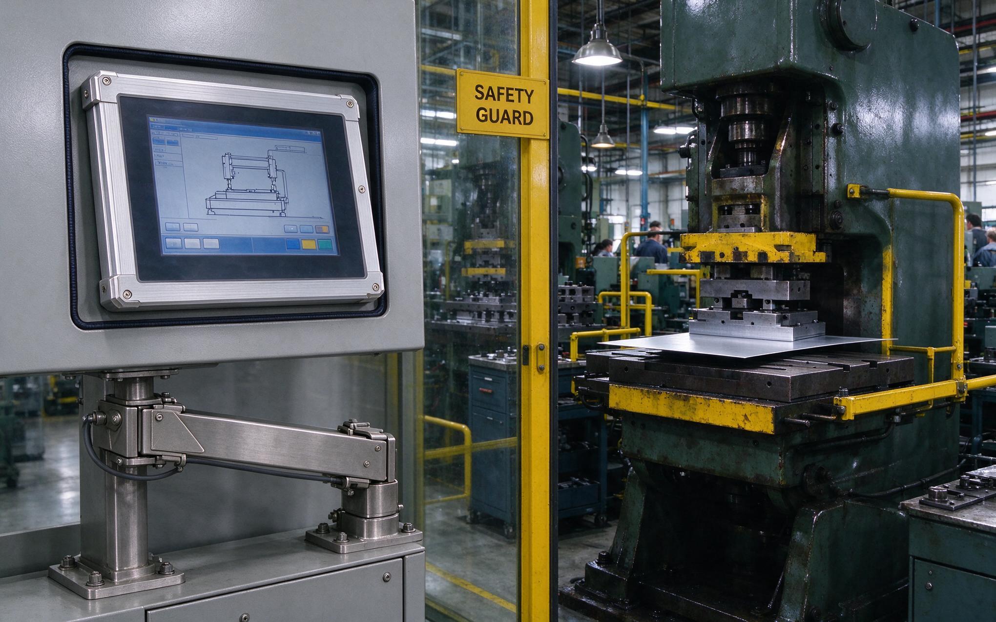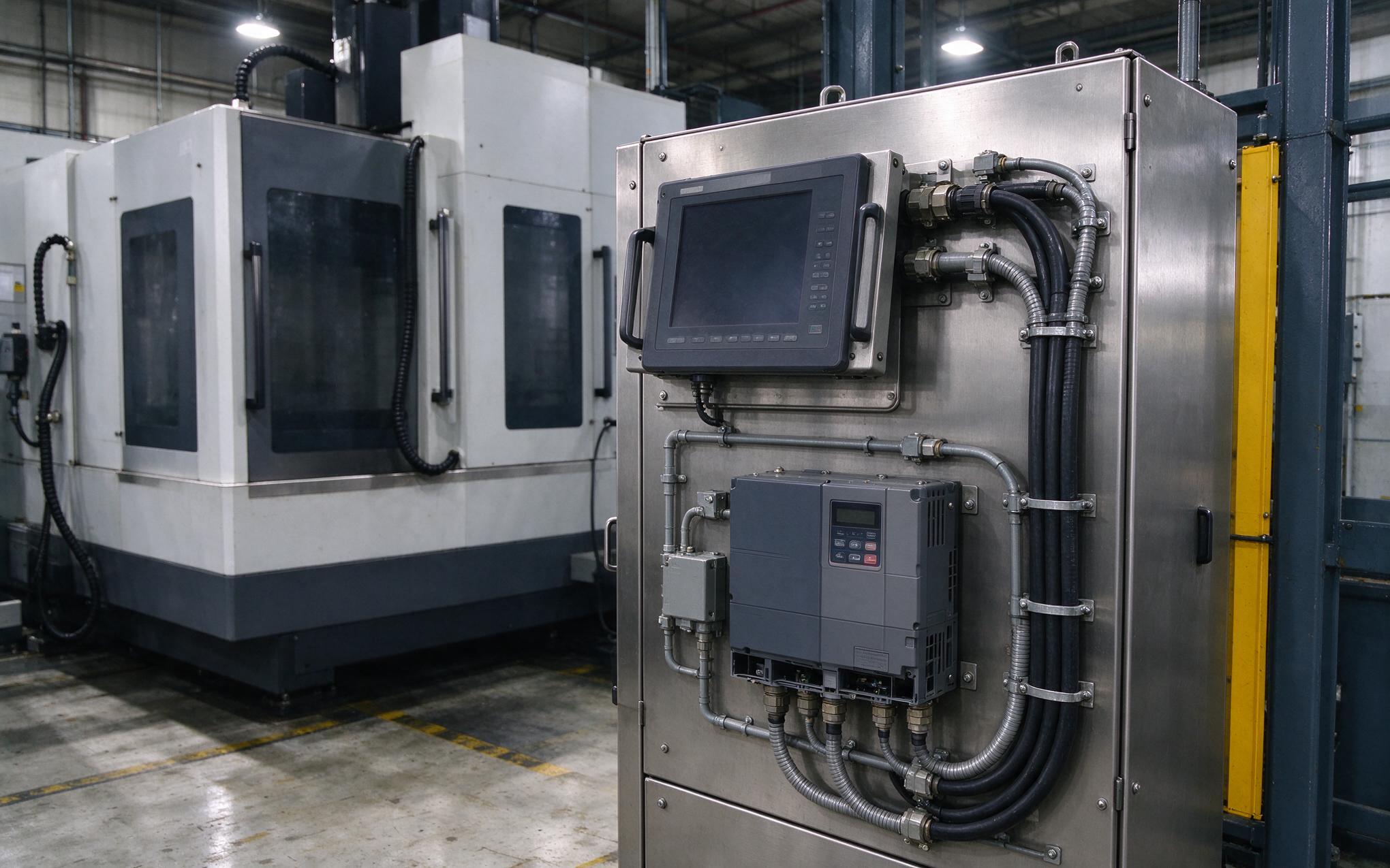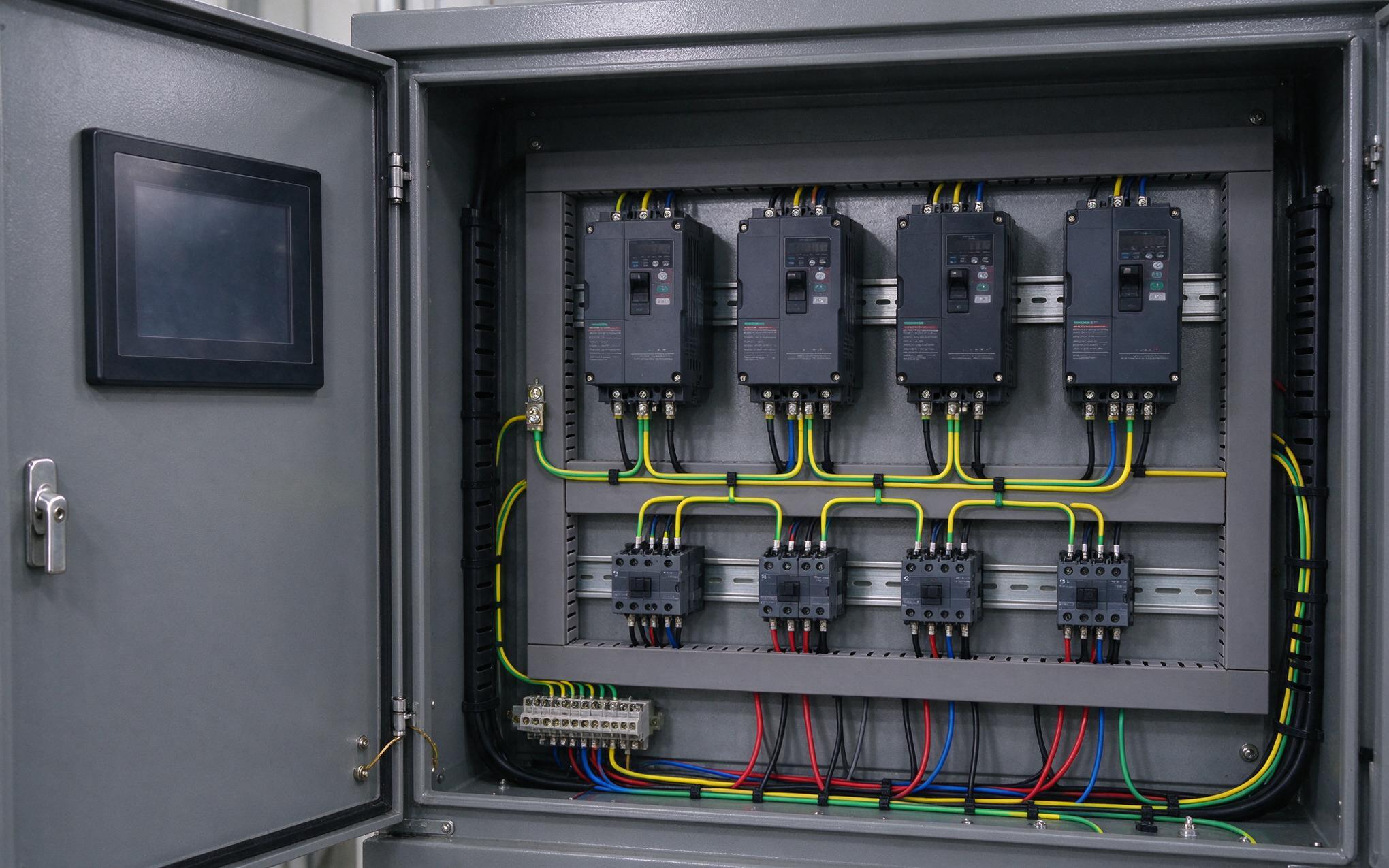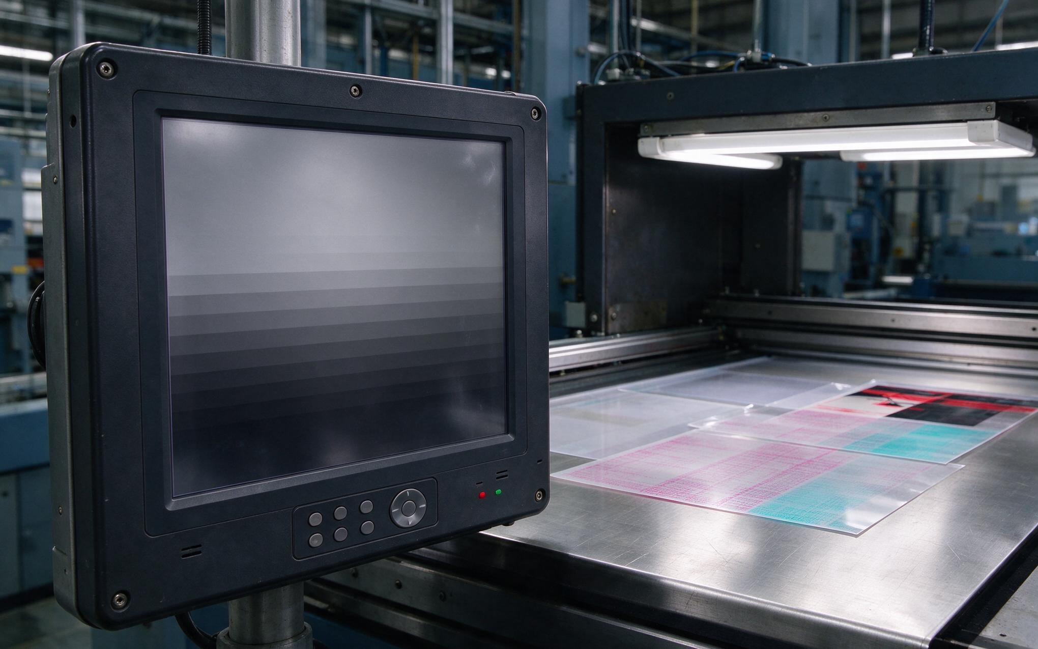
Four industrial panel monitors share one 16 A branch breaker on a packaging line, and on a cold Monday startup the breaker trips the instant all four screens power up together. A single unit starts cleanly, so the fault is not a short circuit. It is the capacitor charging pulse from every display landing on the magnetic trip element in the same millisecond. Called inrush current, this pulse is the hidden sizing variable behind display banks on conveyors, sorters, and unheated warehouse floors. Nameplate input current does not predict it, and a larger breaker only masks it. The fix belongs at the device input, where two routes dominate, a passive thermistor and a relay-bypass stage.
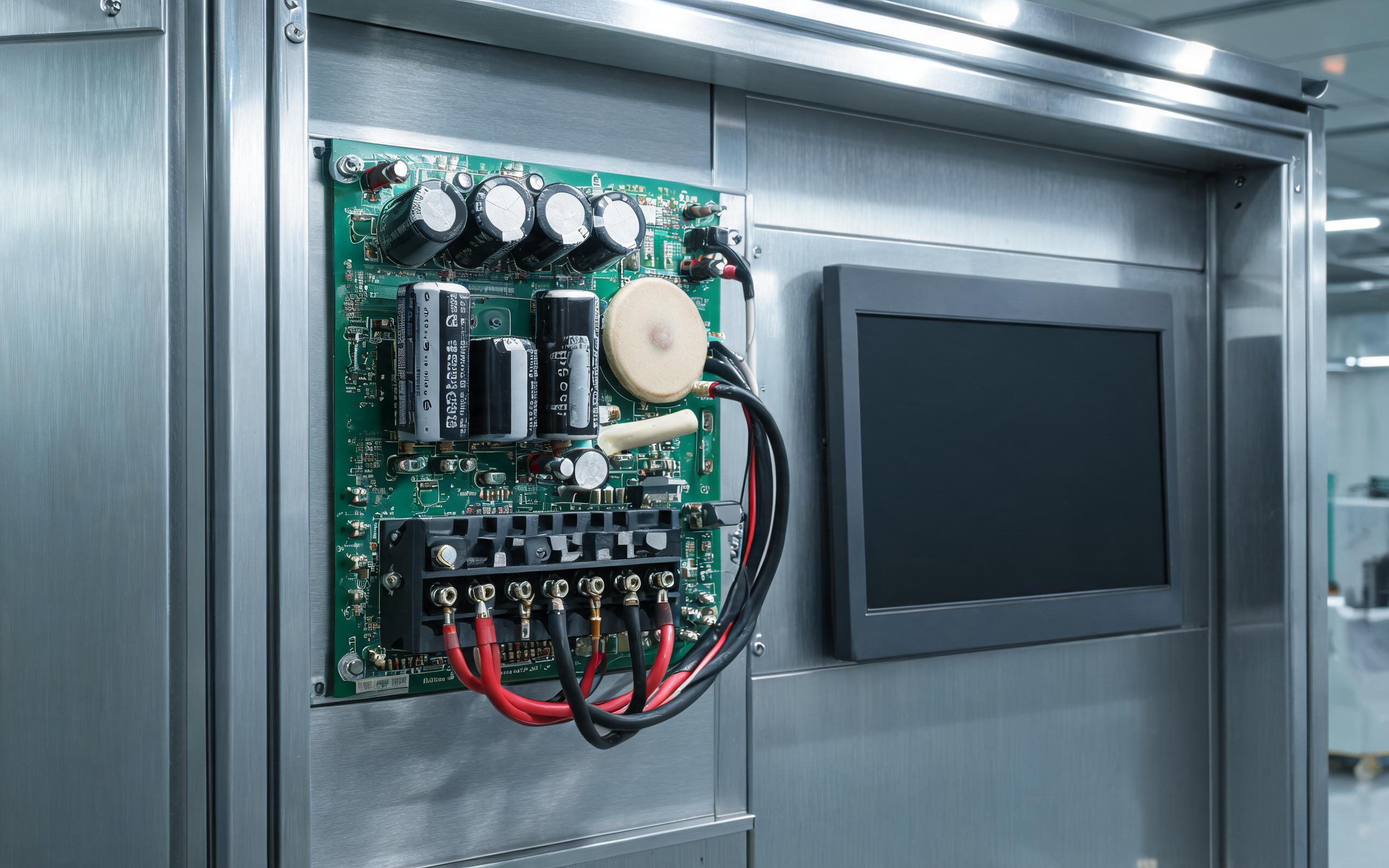
The Inrush Window When an Industrial Panel Monitor Powers Up
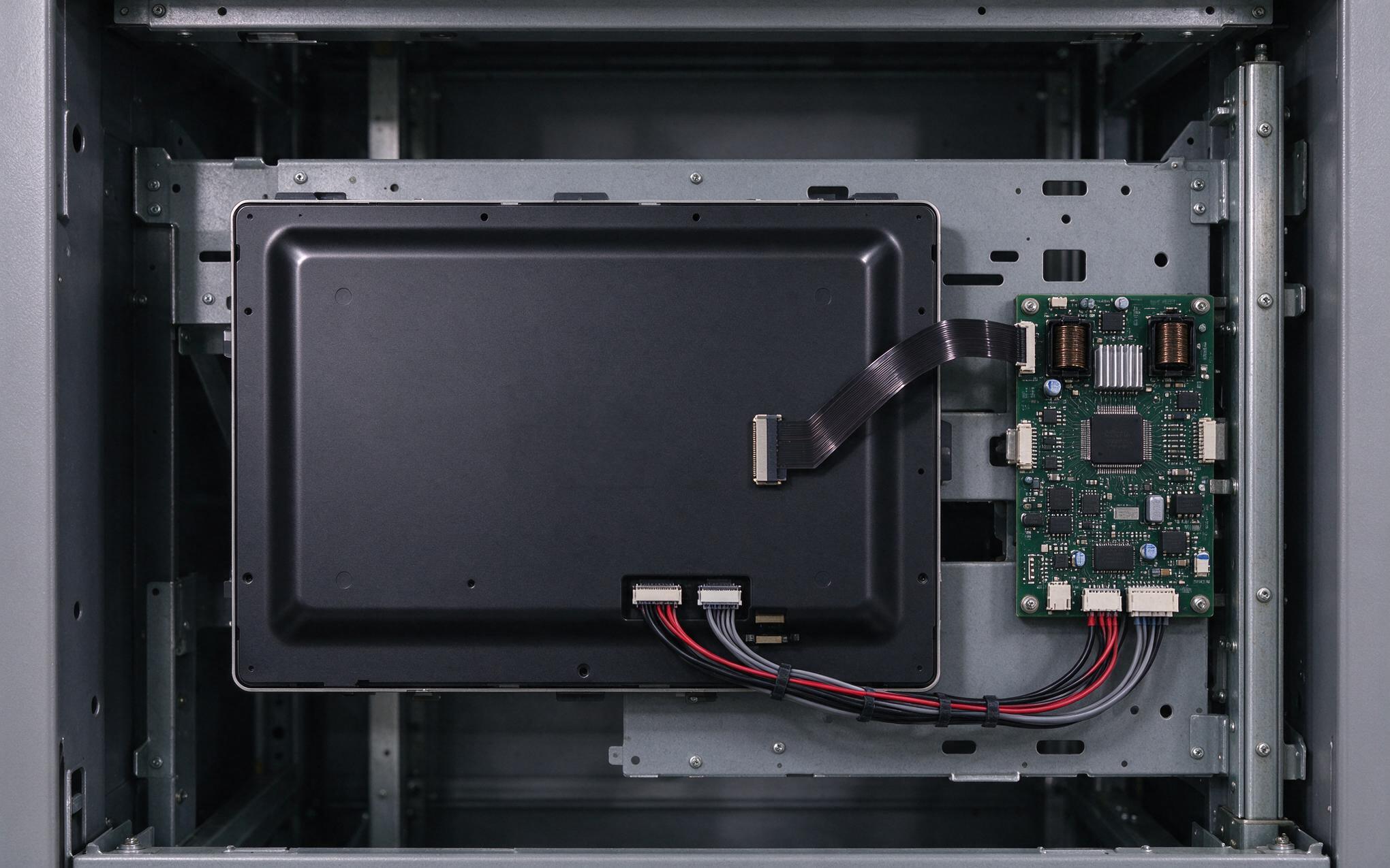
Input-stage designs inspired by KOXIAN power architecture place a limiting element between rectifier and bulk capacitor, since a discharged capacitor behaves nearly like a short at contact closure. Behind the AC inlet, an electromagnetic filter feeds a rectifier charging a large electrolytic capacitor, and with little line impedance the pulse can reach several times the rated current for one to five milliseconds. A breaker’s magnetic element reacts within a single AC half cycle while its thermal strip ignores it, and on a shared branch the peaks add rather than average. Cold ambient conditions sharpen the event as capacitor resistance rises and plant sequences energize whole banks at once.
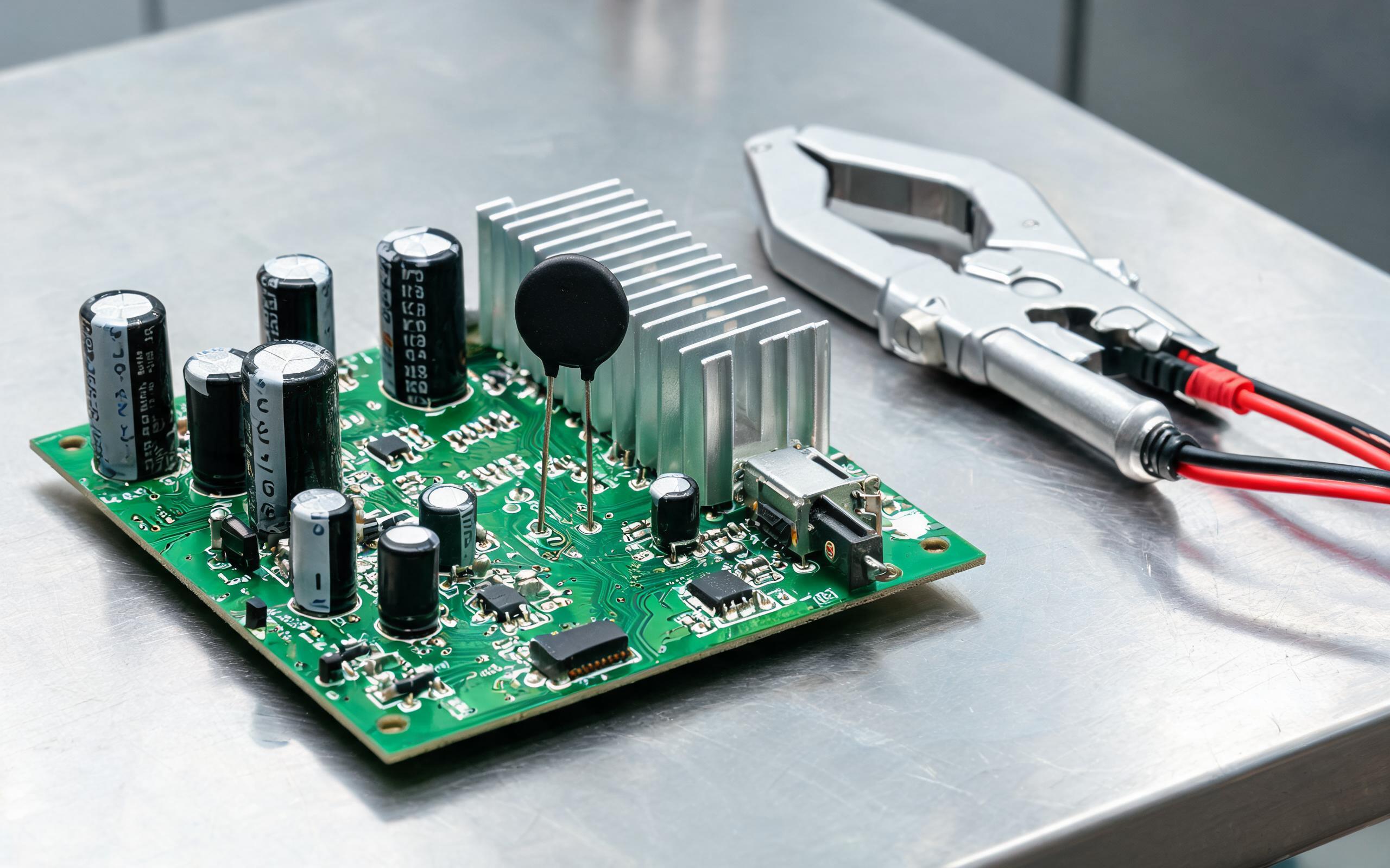
Limiting the Peak with an NTC Thermistor
The common passive answer is a negative temperature coefficient thermistor, a disc-shaped ceramic resistor whose cold resistance, often 5 to 20 ohms in display-sized inputs, holds the charging peak to a safe envelope. As current flows, the device self-heats past 100 C and collapses below an ohm, so steady-state loss stays small with no control circuit. Selection balances three ratings, cold resistance at 25 C, continuous current, and joule energy per start. Limits remain: constant loss and voltage drop, open-circuit end-of-life failure, and a hot restart of an industrial panel monitor within roughly a minute finds the disc still warm and barely limiting. Those trade-offs suit industrial monitors started once per shift, not panels cycling power repeatedly.
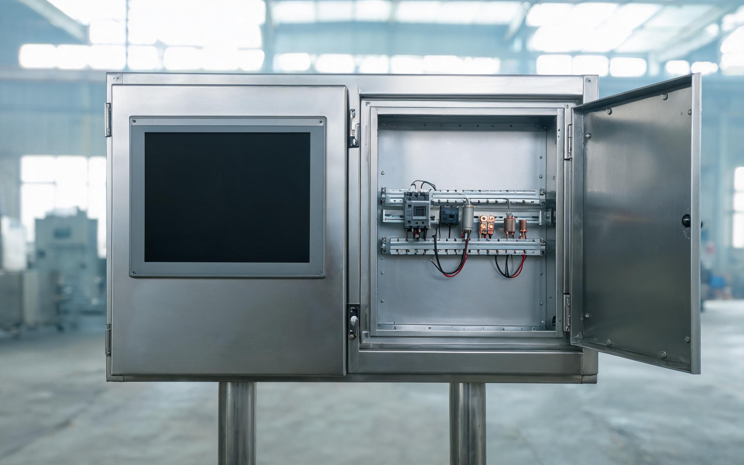
After the Charge Pulse, the Relay-Bypass Route
The alternative keeps a fixed resistor in the charge path only briefly. A wirewound resistor limits the pulse, and in an industrial panel monitor a relay contact closes across it once the supply reports a stable rail, tens of milliseconds later, removing it for the rest of the run. Steady-state loss then approaches zero, restart timing no longer depends on a cooling disc, and the same peak envelope applies cold or hot. The costs are a power-good driven control winding and a contact pair rated for inrush make-and-break cycles, timed never to close under fault current. A solid-state relay variant removes the mechanical contact at the price of heat sinking. That is why a rugged industrial monitor built for frequent cycling tends toward this route.

Which Limiter Fits a Multi-Monitor Branch
Selection starts with measurement, not nameplate watts: capture the peak current, duration, and pulse energy of one industrial panel monitor cold start, then multiply across the units starting together. Compare it with the breaker magnetic threshold under its IEC 60898 curve, commonly five to ten times rated for a C-curve device, before accepting the wiring. Where added stages are ruled out, staggered relay sequencing energizes units a fraction of a second apart, spreading peaks across AC cycles. The sealed input stage used in the KOXIAN G1 series pairs a thermistor with a relay bypass, a layout that holds the hot-restart peak inside the cold-start envelope while avoiding constant series loss. Either way, breaker rating, cable sizing, and limiter should be chosen as one coordinated system, not three separate purchases.
Inrush current, not steady load, decides whether a bank of industrial panel monitors survives a cold group start. The thermistor offers a two-terminal limiter whose steady loss and hot-restart gap suit single displays, while a relay-bypass stage delivers repeatable peaks at the cost of a control stage and contact selection. Breaker curve, pulse energy, restart behavior, and branch count should be settled together on the bench with a current probe rather than after a winter trip. Specified that way, display banks start together without taking the line down with them.