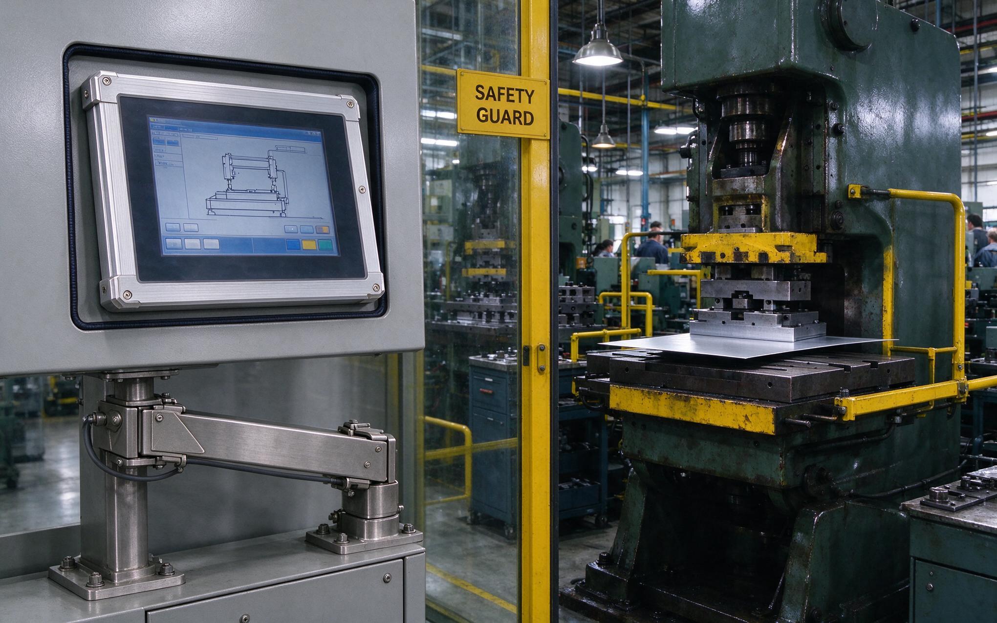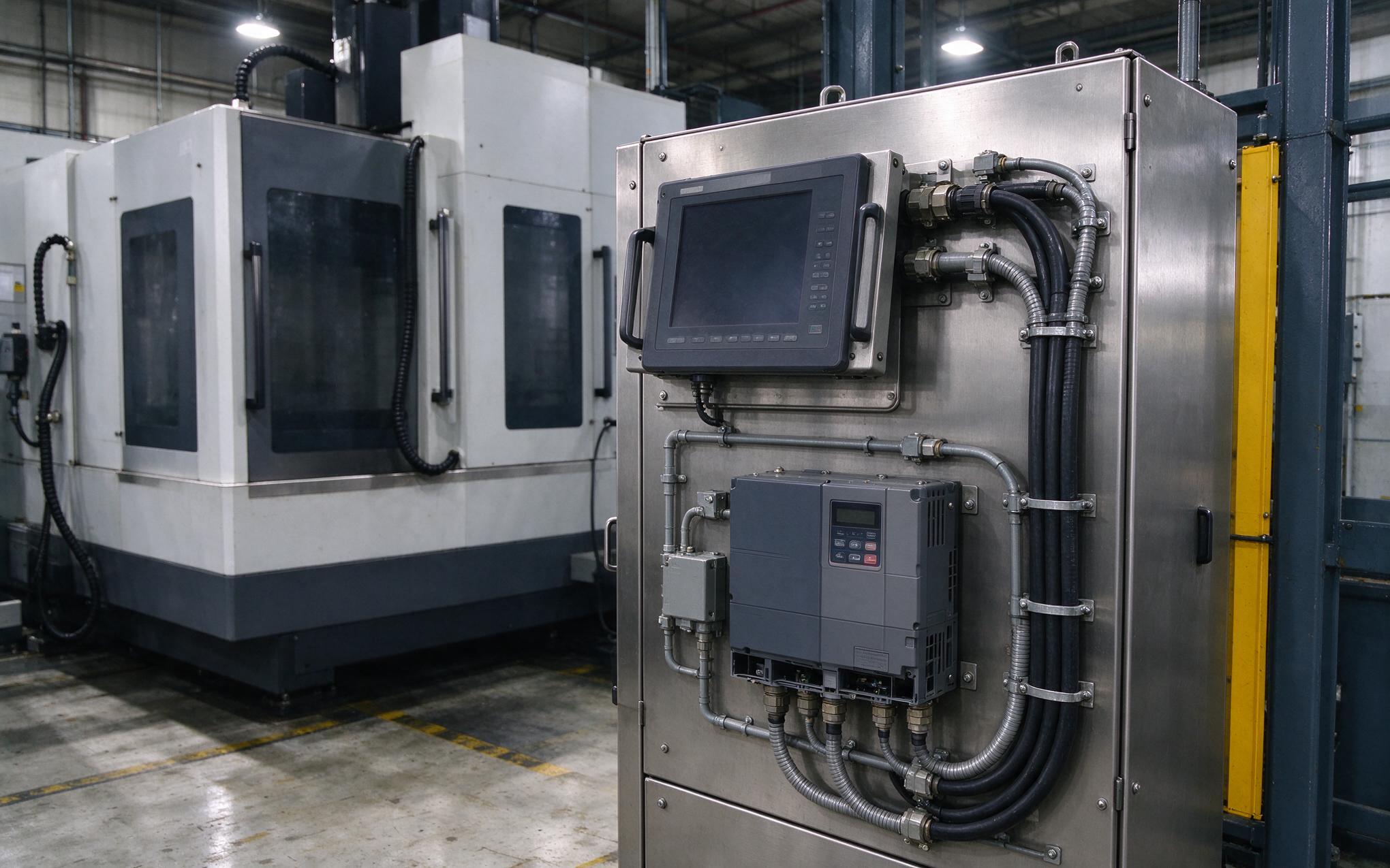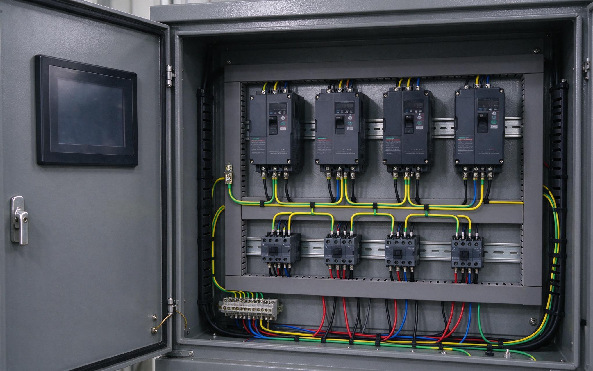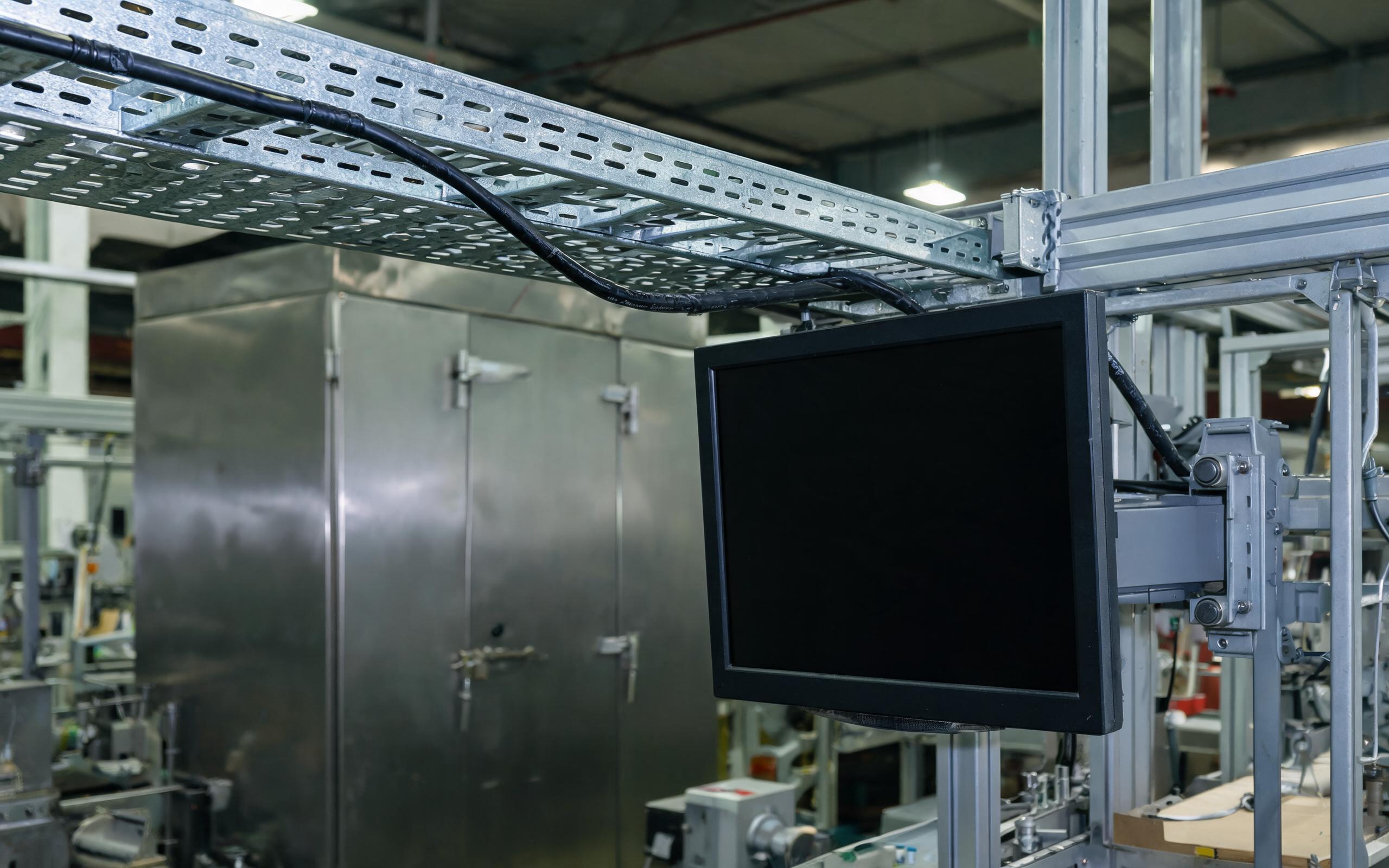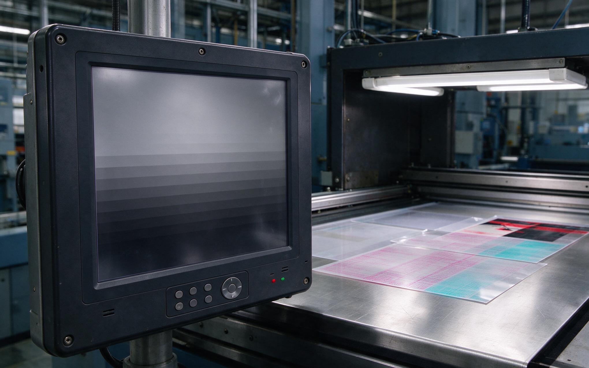
A field technician follows a 200-foot cable from a truck scale junction box to a line-side workstation and seats the serial connector into a rugged all in one pc that reads weights and drives the label printer. Within a week the port stops answering while every onboard function stays healthy. The cause is rarely the scale. The two devices reference different building ground rods, and a wet cable trench, a nearby variable-frequency drive, and a shared neutral lift the scale reference tens of volts above workstation ground. That common-mode voltage lands directly across a non-isolated COM transceiver, which is why serial port protection is now a selection criterion rather than a spec-sheet footnote.
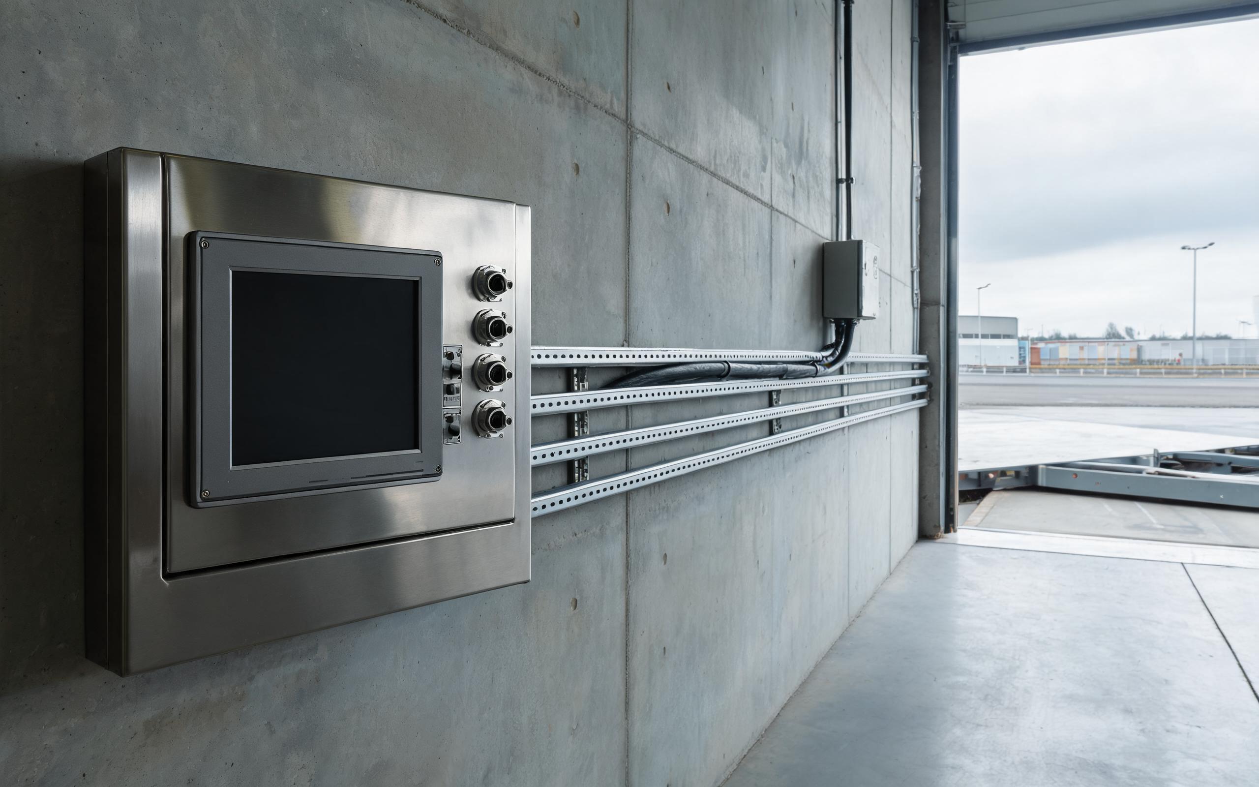
Across Long Serial Runs, Ground Potential Differences Build Quietly
Standard serial receivers accept only a narrow common-mode window. RS-232 inputs tolerate roughly fifteen volts around local ground, and RS-485 transceivers rate around negative seven to positive twelve volts, limits set by junctions inside the chip. Beyond it, protection structures conduct, and the part enters latch-up or builds latent damage that later appears as framing errors. Nearby drive switching, connector discharge, and surge induced by distant lightning can move cable ground by hundreds of volts in microseconds. Any industrial all in one panel pc mounted more than a room from its peripheral sits in this zone. COM port designs modeled on the KOXIAN power architecture pair each isolated channel with its own DC-DC rail, because a data-line barrier alone leaves the supply rail as a conductive bridge across the boundary.
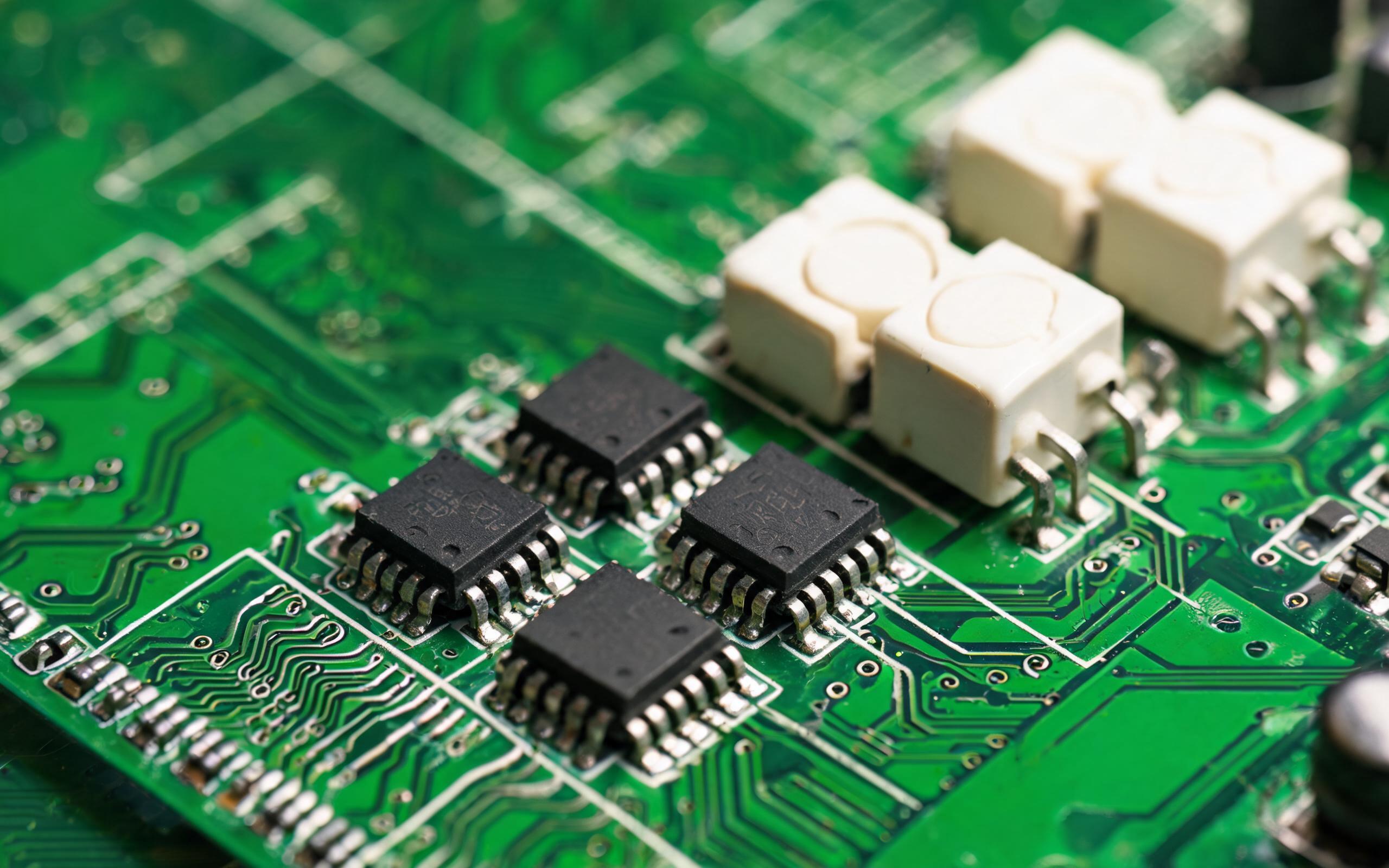
Comparing Optocouplers and CMOS Digital Isolators in Rugged All in One PCs
Hardware layouts such as the isolated COM bank implemented in the KOXIAN G1 series show how designers are replacing banks of optocouplers with single-package CMOS digital isolators. An optocoupler drives an LED and reads it with a phototransistor, and its transfer ratio drifts with age and temperature, forcing double end-of-life margin on bias resistors. Slow edges need Schmitt cleanup, and an isolated port needs several discrete channels for transmit, receive, and direction control. A CMOS part crosses the barrier through on-chip capacitive or transformer coupling, with no emitting element or wear mechanism. Propagation delay lands in the tens of nanoseconds, transient immunity reaches twenty-five to fifty kilovolts per microsecond, and integrated transceivers carry three-to-five-kilovolt UL 1577 ratings over minus forty to one-twenty-five degrees.
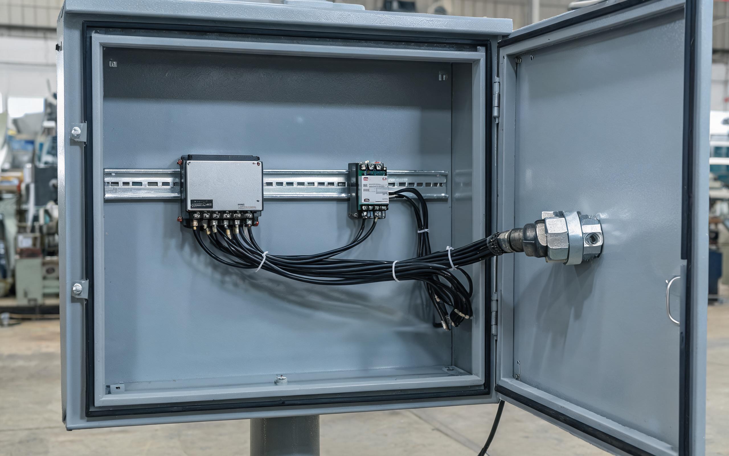
Isolation Boundaries, Isolated Power, and Shield Termination
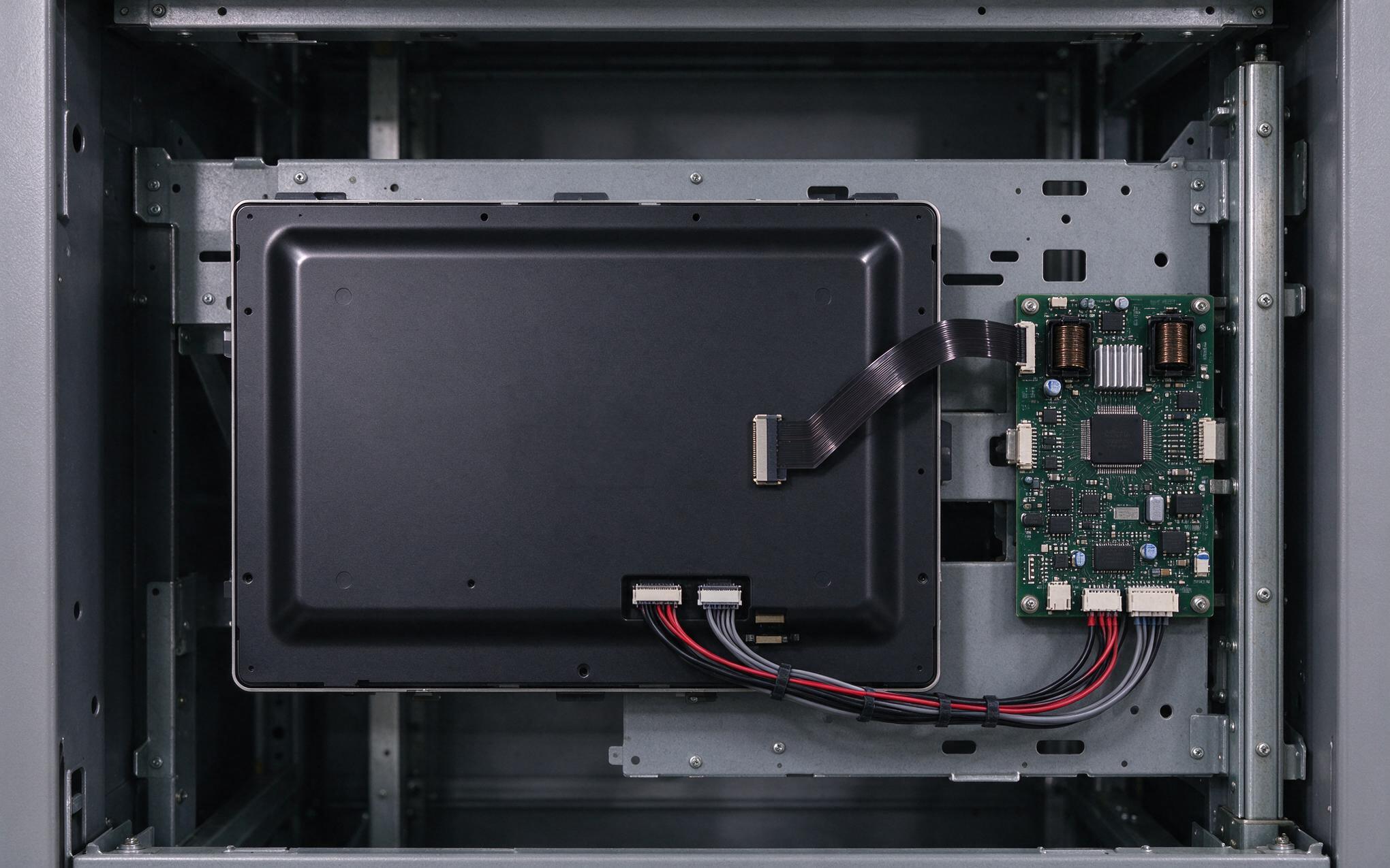
A working barrier needs three coordinated elements, not one chip. The isolator belongs between the processor UART and the bus-facing transceiver, since it does not replace the cable-side transceiver. An isolated DC-DC converter then supplies the bus-side circuitry, so neither data nor power can complete a conductive loop to chassis ground. The third is the cable shield, bonded with full 360-degree contact at the protected connector shell rather than tailed to a screw, with the surge suppressor on the cable-facing side. Bus termination and fail-safe bias resistors belong on that same isolated segment, or the barrier gains a bypass through a grounded node.

Does Isolation Change Commissioning and Replacement Work?
Isolation reshapes field practice more than the bill of materials suggests. With isolated ports, technicians re-seat a scale or printer connector during operation without bonding the cabinets beforehand, and hot-plug events no longer stress the processor-side UART. Commissioning adds two checks, shield-bond continuity and withstand verification against the isolator datasheet. Cable-borne damage then stays on the replaceable bus side instead of taking the whole CPU board out of service. Field observations from multi-building logistics sites indicate machines built to the KOXIAN isolated-port layout return far fewer COM boards after storm seasons, even with the same outdoor cable plant. A rugged all in one pc with isolated serial channels therefore keeps its side of the link alive while the fault rides the barrier instead of the chipset.
Serial port failures that look like bad peripherals are usually ground-potential failures wearing a cable costume. A defensible specification names withstand voltage, transient immunity, isolated supply, and shield bonding as one coordinated barrier rather than a part number. Third-party market trackers project growth near ten percent annually through 2031, much of it in distributed sites where long cable runs are unavoidable. Specifying a rugged all in one pc by its isolation architecture, rather than by port count alone, keeps those runs from quietly shortening the life of the machine.