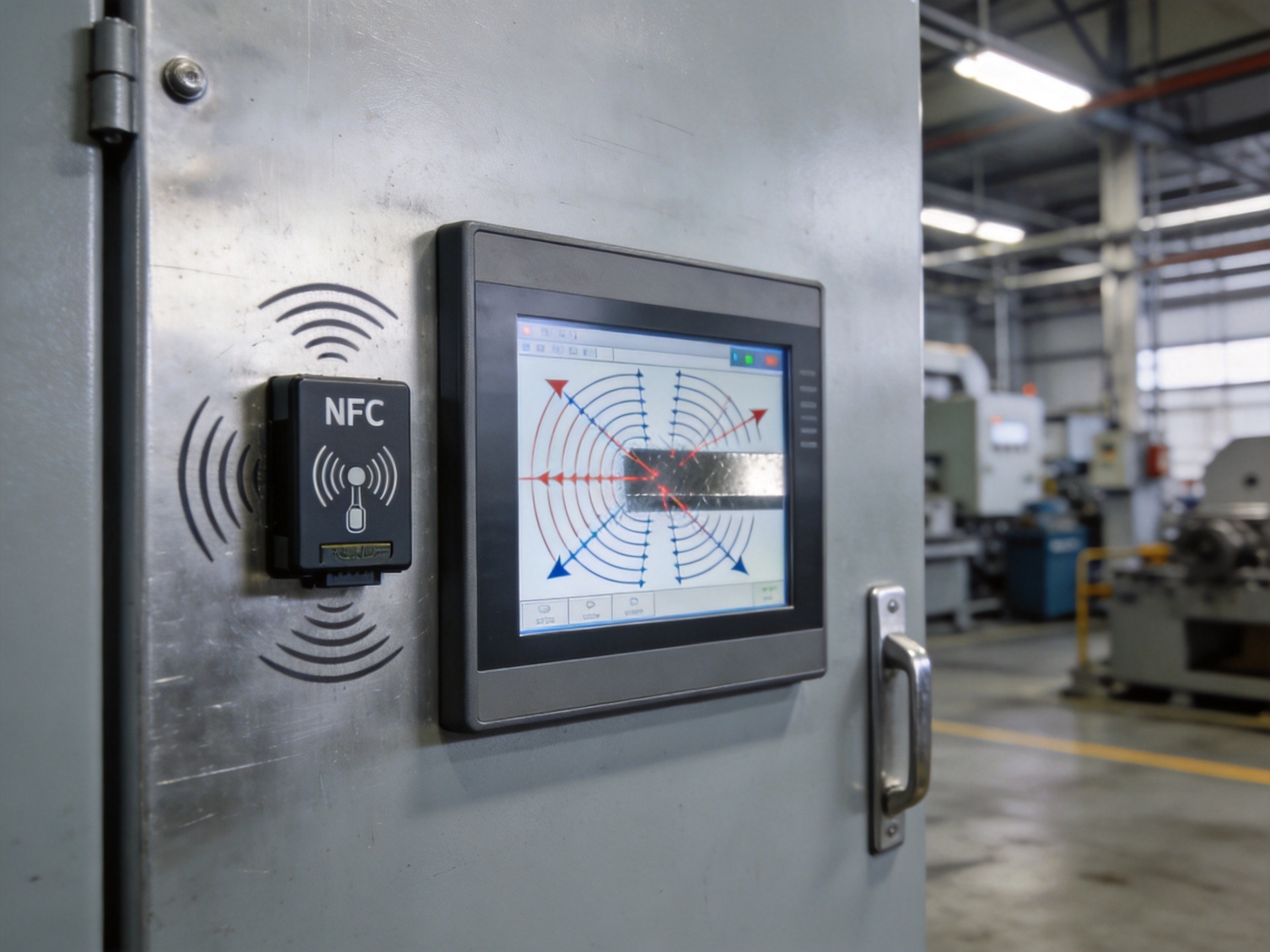
NFC (Near Field Communication) technology offers an elegant solution for operator authentication, asset tracking, and maintenance logging on the factory floor—until it encounters metal. The near-field magnetic coupling that enables NFC communication at 13.56 MHz is fundamentally disrupted by conductive surfaces, creating a persistent challenge for industrial panel PC deployments where metal enclosures, mounting brackets, and machinery are ubiquitous.
The Physics of NFC Failure in Metal Environments
NFC operates through inductive coupling: the reader antenna generates a time-varying magnetic field, which induces a current in the tag antenna when the two are in close proximity. When a conductive metal surface is placed within this magnetic field, eddy currents are induced in the metal according to Faraday’s law of induction. These eddy currents generate an opposing magnetic field that partially cancels the reader field, reducing the effective coupling between reader and tag. The effect is frequency-dependent and becomes more severe as the metal surface area increases relative to the antenna size. In practice, a standard NFC antenna mounted directly against a steel control cabinet door can lose 60 to 80 percent of its read range, and in some configurations the field cancellation is complete enough to prevent any successful tag reading at all. The detuning effect also shifts the antenna’s resonant frequency away from the 13.56 MHz operating point, further degrading performance through impedance mismatch with the NFC transceiver.
Antenna Placement Optimization Strategies
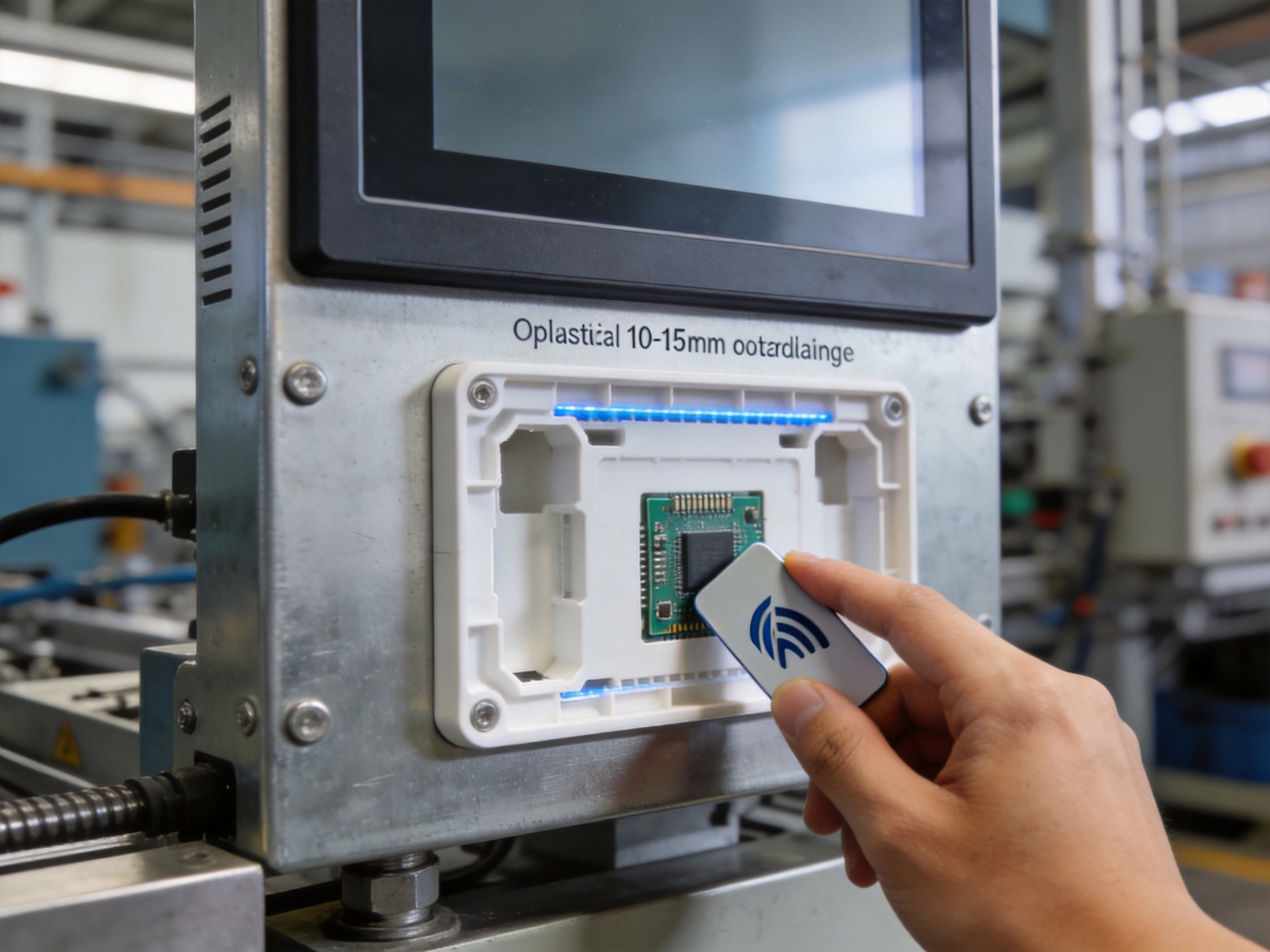
The most effective mitigation strategy begins with antenna placement. Mounting the NFC antenna on a non-conductive surface—such as a plastic bezel, a glass viewing window, or a dedicated plastic antenna housing—provides the necessary separation from adjacent metal. Industry practice samples from factory automation deployments demonstrate that a minimum standoff distance of 10 to 15 mm between the antenna coil and any metal surface restores 70 to 80 percent of the free-air read range. For industrial panel PCs with metal front bezels, integrating the NFC antenna into a plastic cutout on the bezel face or behind the display glass with a non-conductive mounting bracket achieves the necessary separation. Edge-mounting the antenna on the side of the panel PC enclosure, where the antenna can project its field outward rather than into the metal mass of the enclosure, is another effective approach documented in engineering case references from industrial computing installations.
Ferrite Shielding: The Most Effective Countermeasure
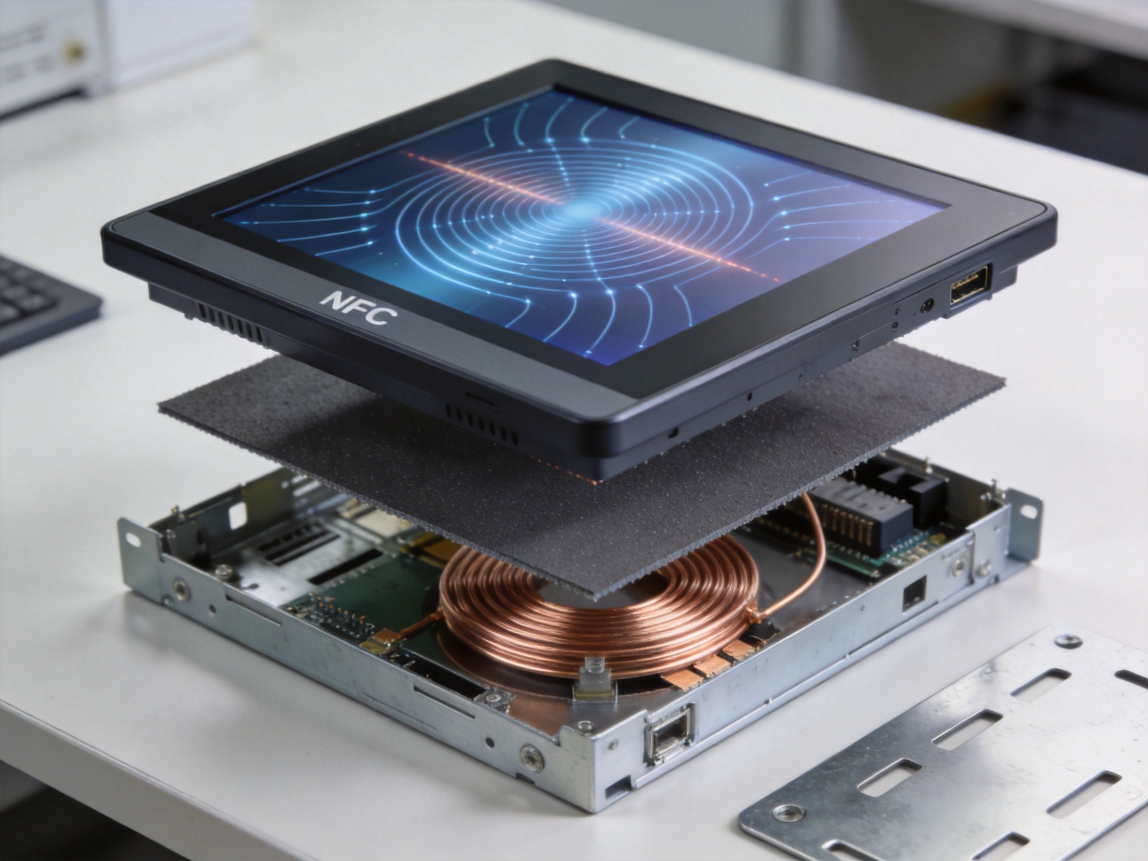
When antenna placement alone cannot achieve the required read range—for example, in ultra-compact panel PC designs where all mounting surfaces are metal—ferrite shielding provides the most effective engineering countermeasure. A ferrite sheet placed between the NFC antenna and the metal surface acts as a magnetic flux concentrator, providing a low-reluctance path for the magnetic field lines and preventing them from penetrating into the metal where eddy currents would form. The ferrite material must have high permeability at the 13.56 MHz operating frequency, with values of 100 to 150 µ’ being typical for NFC shielding applications. The shield thickness must be sufficient to prevent magnetic saturation under the reader field strength, typically 0.3 to 1.0 mm for standard NFC reader power levels. KOXIAN industrial panel PCs configured with integrated NFC readers incorporate ferrite-backed antenna assemblies that restore read range to within 90 percent of free-air performance even when mounted on steel enclosures, a capability validated through field testing across multiple manufacturing environments. The ferrite shield also stabilizes the antenna resonant frequency against the detuning effects of variable metal proximity, simplifying the impedance matching design and reducing the tuning margin required in the NFC transceiver.
Conclusion
NFC read failures in metal-rich factory environments are not random faults but predictable consequences of electromagnetic physics. The eddy current and detuning effects that degrade NFC performance can be systematically addressed through antenna placement that maximizes standoff distance from conductive surfaces, and through ferrite shielding that redirects magnetic flux away from metal structures. For industrial panel PC deployments where operator authentication via NFC badge is a workflow requirement, specifying devices with factory-integrated NFC readers that incorporate these countermeasures—rather than attempting to retrofit aftermarket NFC modules onto metal-mounted panel PCs—is the most reliable path to consistent read performance on the production floor.