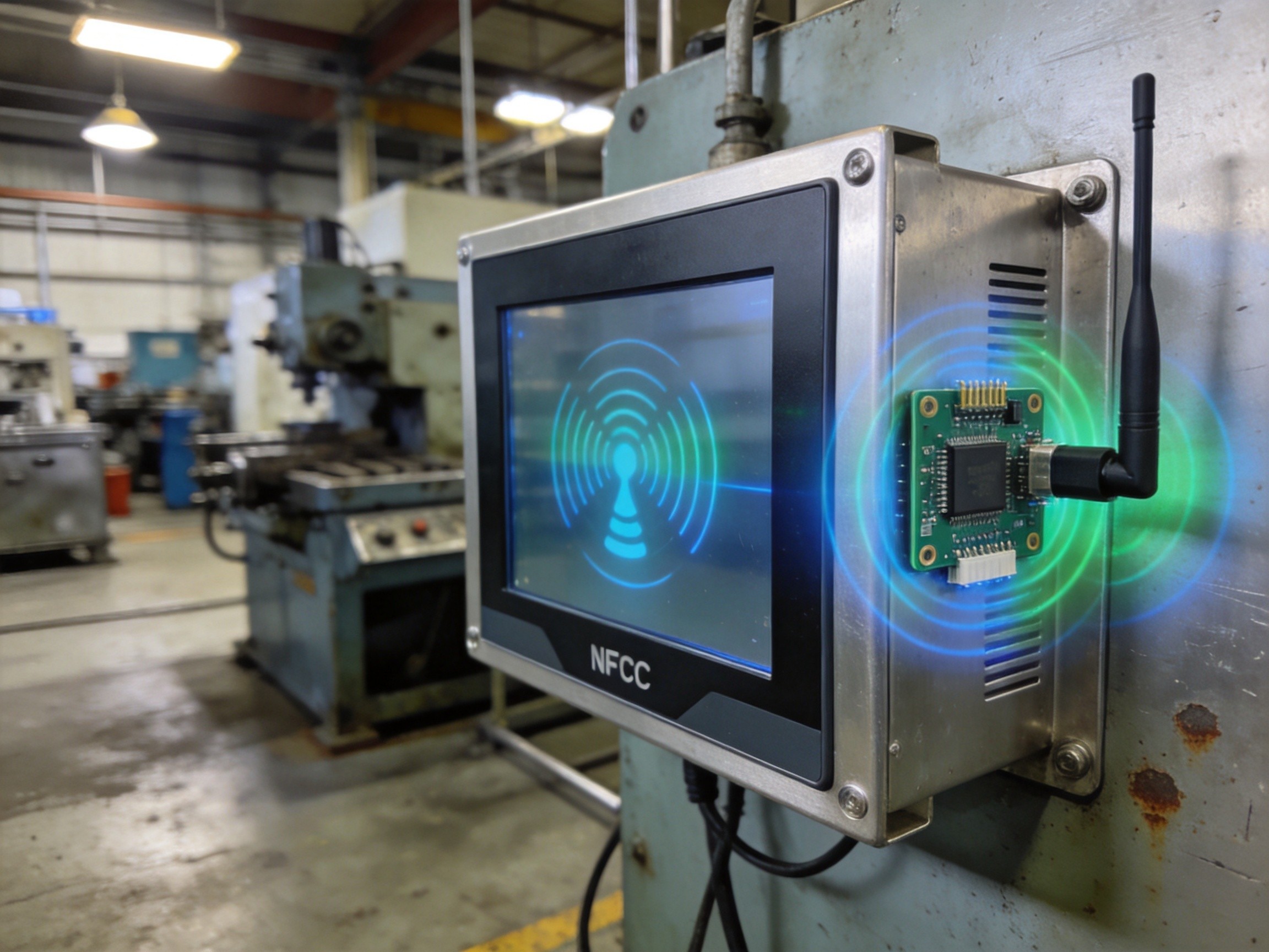
Touchscreens have become so reliable that most operators take them for granted. Tap, swipe, pinch—the gestures are muscle memory. But beneath the glass surface, a degradation mechanism operates on a microscopic scale that can eventually render even the most robust industrial touch panel unresponsive. The culprit is ITO micro-crack propagation: the gradual fracturing of the indium tin oxide electrode layer that makes projected capacitive touch technology possible. Understanding this failure mode is essential for anyone deploying touchscreens in environments where vibration, thermal cycling, and mechanical stress are daily realities.
The Structure of ITO Touch Electrodes
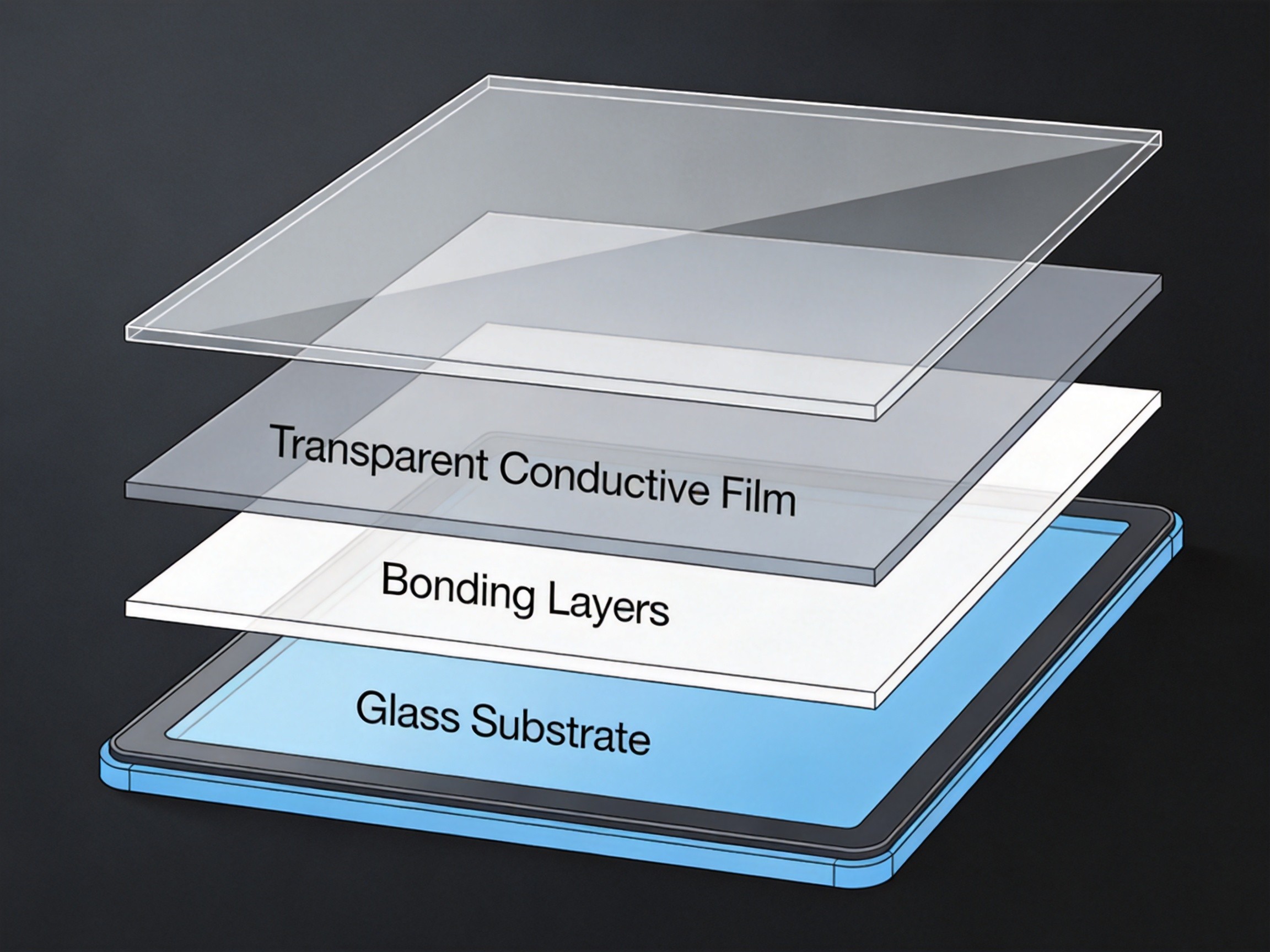
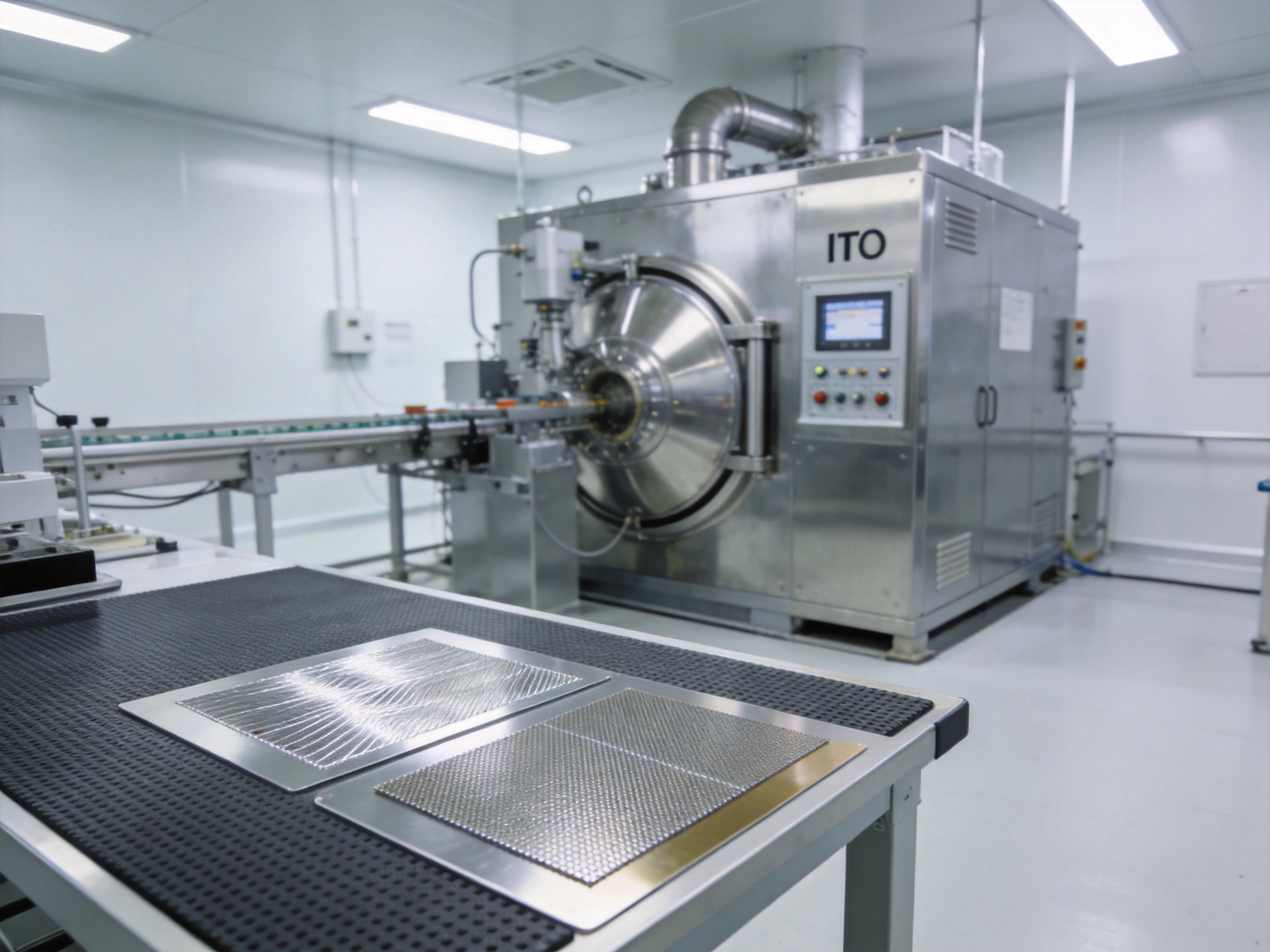
ITO is a transparent conductive oxide deposited as a thin film—typically 100 to 200 nanometers thick—onto a glass or PET substrate. The film is patterned through photolithography into a grid of microscopic electrode rows and columns. When a finger approaches the surface, it disturbs the electrostatic field between these electrodes, and the touch controller IC triangulates the touch location. The critical limitation is that ITO is fundamentally brittle. Unlike metals that deform plastically, ITO fractures at very low strain thresholds—typically less than one percent elongation. In industrial panel PCs deployed on vibrating machinery, inside vehicles, or in outdoor kiosks subject to daily thermal swings, repeated micro-strain accumulates at the electrode grain boundaries. KOXIAN industrial touch displays use a sputtered ITO deposition process with optimized annealing that produces a finer, more uniform grain structure, reducing stress concentration points at grain boundary intersections.
Micro-Crack Initiation and Propagation Mechanisms

Crack initiation typically begins at three weak points in the touch sensor stack. The first is the flex bond region, where the flexible printed circuit carrying signals from the touch controller is bonded to the ITO electrodes using anisotropic conductive film. Repeated thermal expansion mismatch between the FPC and the glass substrate concentrates shear stress at the bond pads, eventually causing the ITO traces to crack at the bond interface. The second initiation site is the electrode crossover points, where the row and column electrodes intersect with a thin dielectric layer between them. The additional thickness at these intersections creates a topographical stress concentrator. The third is edge defects from the singulation process—microscopic chips and cracks introduced when the touch sensor glass is cut to size. Once initiated, cracks propagate along grain boundaries at rates that accelerate with each thermal cycle. A 20-degree Celsius temperature swing can produce enough differential expansion between the ITO film and the glass substrate to extend existing micro-cracks by several nanometers per cycle.
Symptoms and Detection

The first symptom operators notice is not complete failure but gradual degradation. Touch sensitivity drops in specific regions, requiring firmer presses or multiple taps to register. The touch controller compensates by increasing amplifier gain, but this introduces noise that manifests as random ghost touches. Eventually, as enough electrode traces fracture, entire rows or columns of the touch matrix drop out, creating dead bands aligned with the electrode grid pattern. Diagnostic tools that read the touch controller’s raw signal-to-noise ratio per electrode can identify failing regions before they become operator-visible. For deployments using KOXIAN panel PCs with integrated touch diagnostics, the system can generate predictive maintenance alerts when SNR values for any electrode group drop below a configurable threshold, giving maintenance teams months of lead time to schedule replacement.
Mitigation Strategies and Material Advances
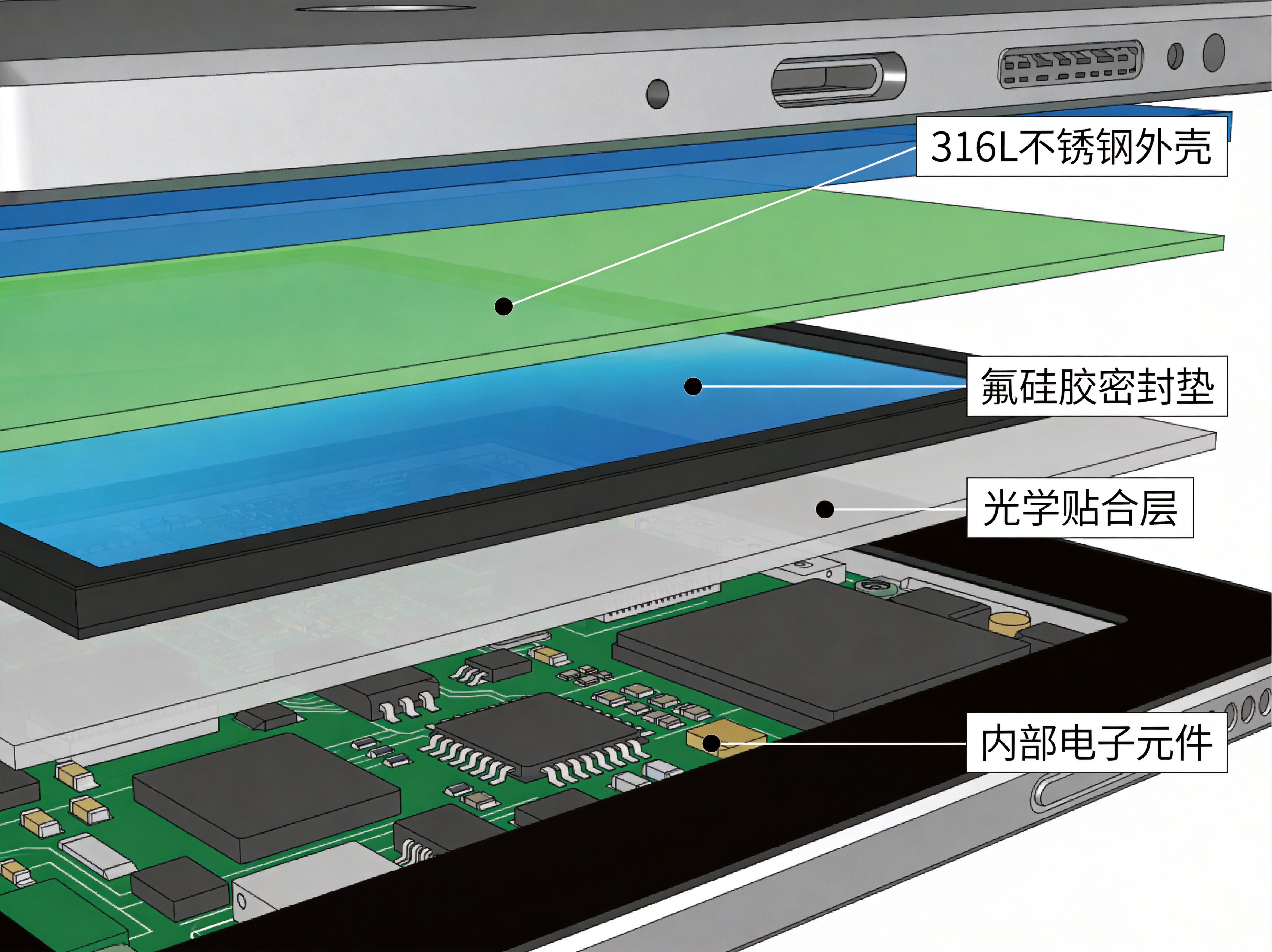
Several approaches mitigate ITO micro-crack risk. At the material level, silver nanowire and metal mesh technologies offer flexible alternatives to ITO, maintaining conductivity at elongations exceeding three percent. At the mechanical design level, decoupling the touch sensor from the display module using compliant optical bonding adhesive absorbs strain before it reaches the ITO layer. At the firmware level, modern touch controllers implement electrode health monitoring that dynamically re-routes touch detection around dead electrode segments. The most effective strategy combines all three: selecting flexible electrode materials, using compliant bonding in the display stack, and enabling firmware-level electrode health monitoring for early warning of developing problems.
ITO micro-crack propagation is a slow, silent failure mode that can take months or years to manifest. But in environments where touchscreen reliability is non-negotiable, understanding the degradation physics and implementing proactive detection and mitigation gives maintenance teams the lead time they need to act before the operator experiences the first unresponsive tap.