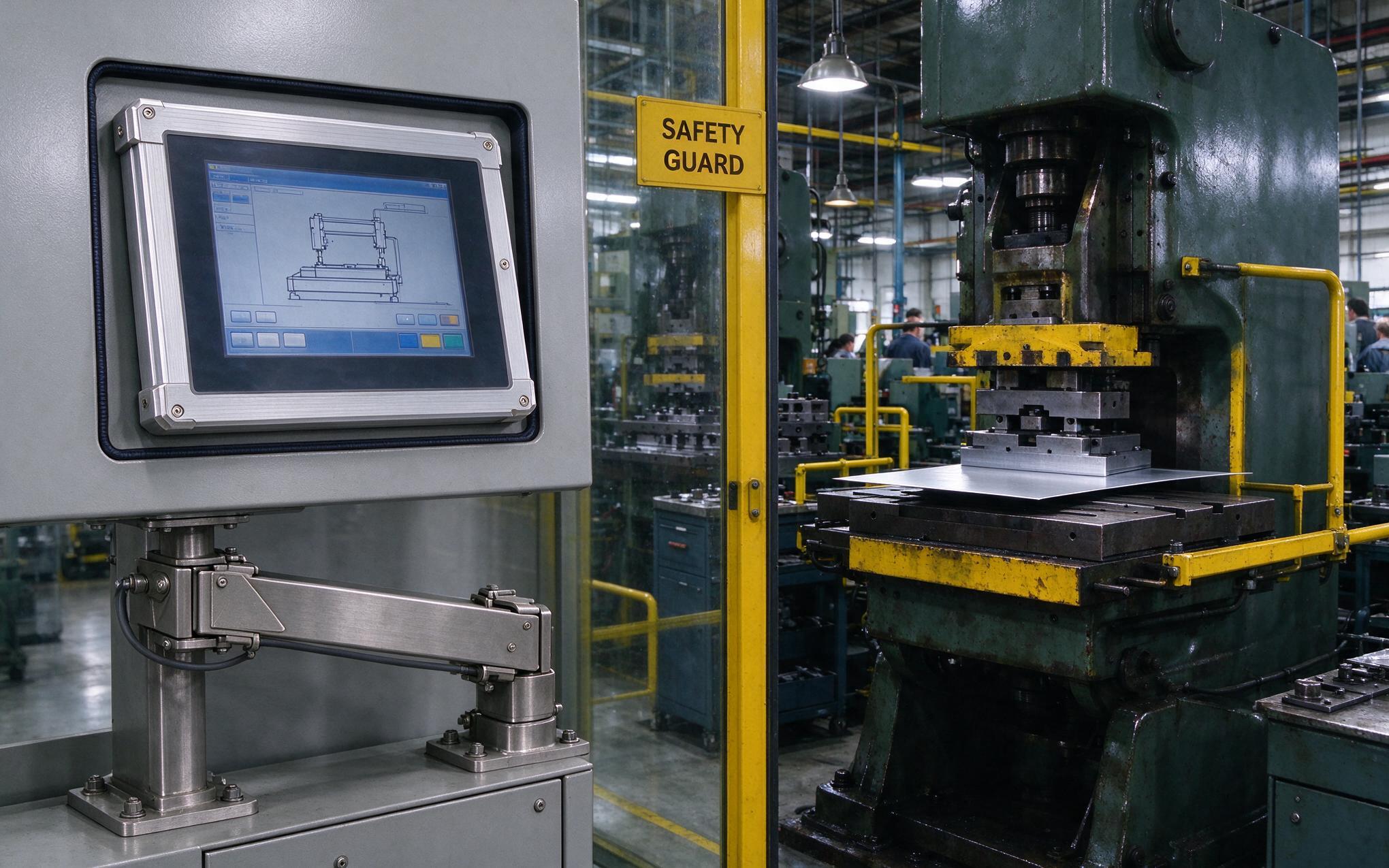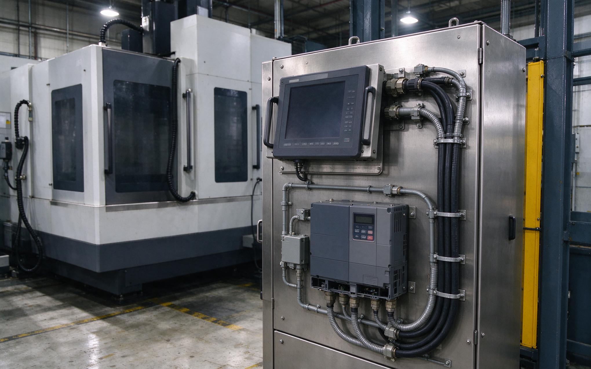
Ghost touches register on the screen every time the variable frequency drive ramps the conveyor motor past 40 Hz. Unintended menu selections appear without any finger contact, and the display flickers with phantom inputs while the operator watches. IEC 61800-3 establishes emission limits for adjustable speed drives, yet compliance at the drive level does not guarantee noise-free operation at nearby equipment. An industrial PC touch screen monitor operating within meters of high-power switching electronics still receives conducted and radiated noise that degrades touch controller signal integrity until legitimate inputs become indistinguishable from background interference.
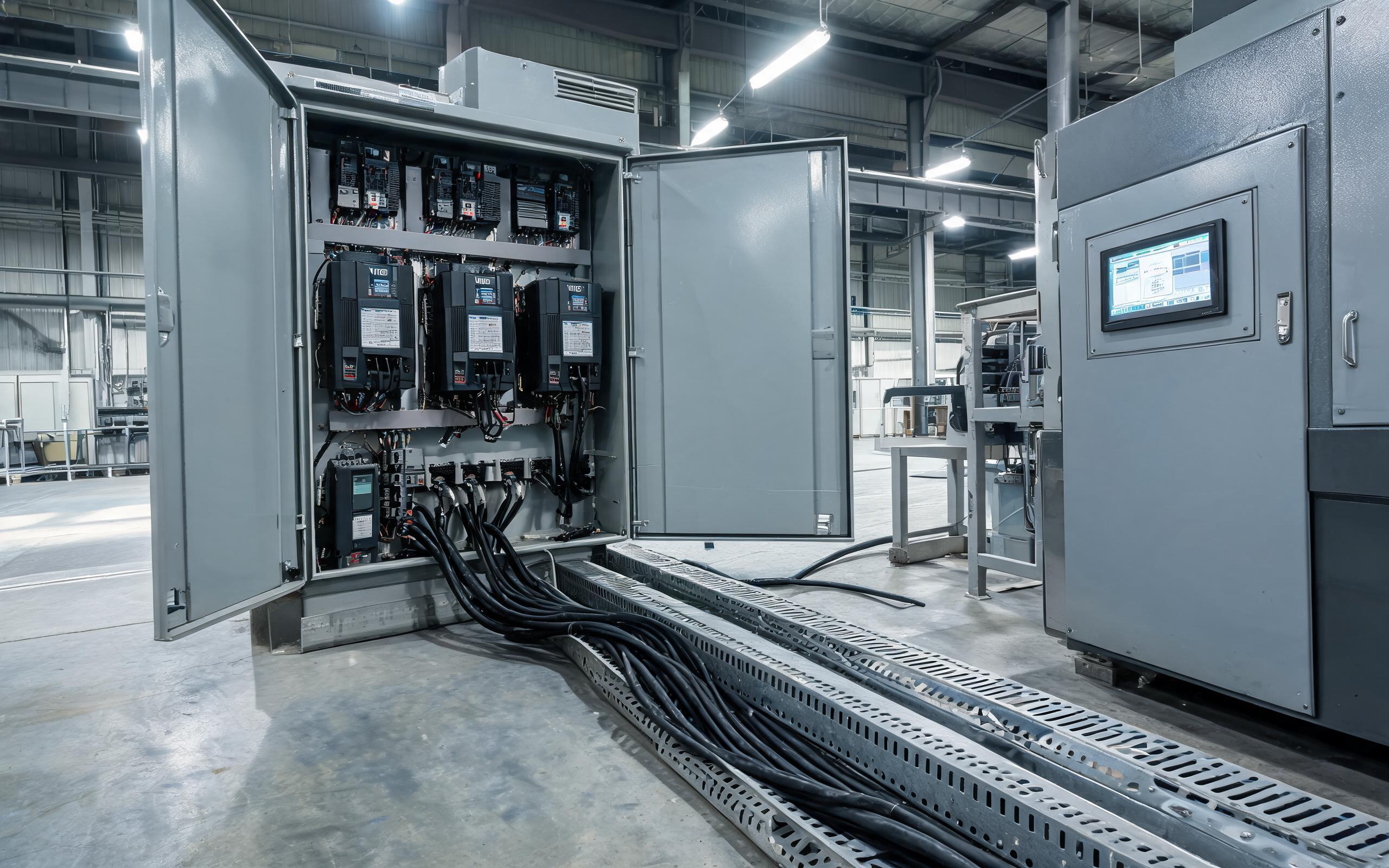
Understanding VFD Noise Coupling into Touch Signal Paths
Variable frequency drives regulate motor speed by switching DC bus voltage into pulse-width-modulated waveforms at carrier frequencies between 2 kHz and 16 kHz. IEC 61800-3 categorizes drive installations into C1 through C4 environment classes and sets conducted emission limits accordingly, but these limits are measured at the drive terminals, not at the equipment receiving the interference. Each switching edge contains harmonic energy extending well into the megahertz range. This energy travels along motor cables as conducted emissions and radiates from unshielded cable runs as electromagnetic fields. When these fields intersect the sensor grid of a projected capacitive touch screen, they induce displacement currents that the touch controller interprets as changes in mutual capacitance. A fanless panel pc mounted adjacent to a drive cabinet faces two coupling paths simultaneously: conducted noise arriving through shared power circuits and radiated noise penetrating through enclosure openings or unshielded front bezels.
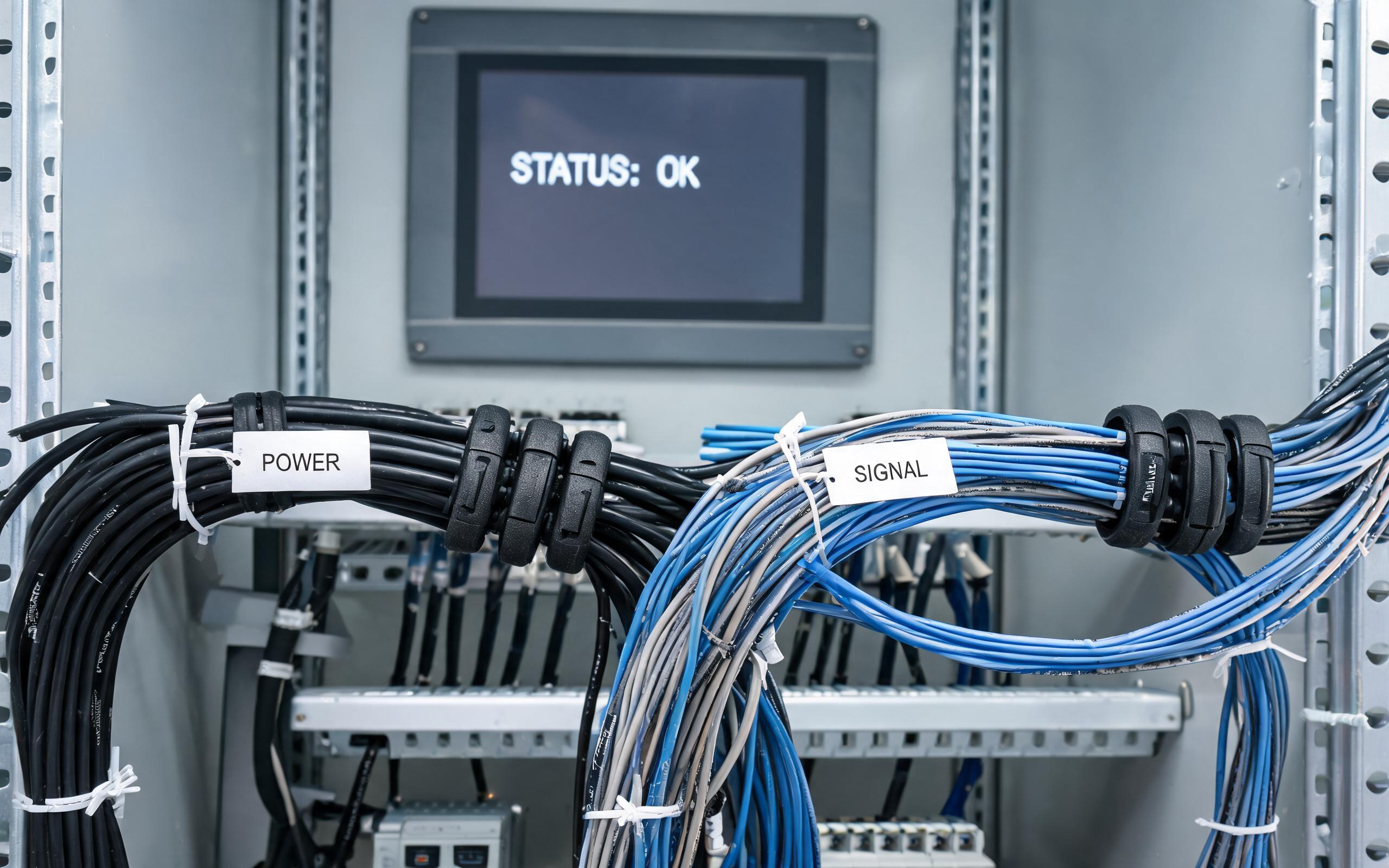
Ferrite Suppression and Cable Routing for Noise Reduction
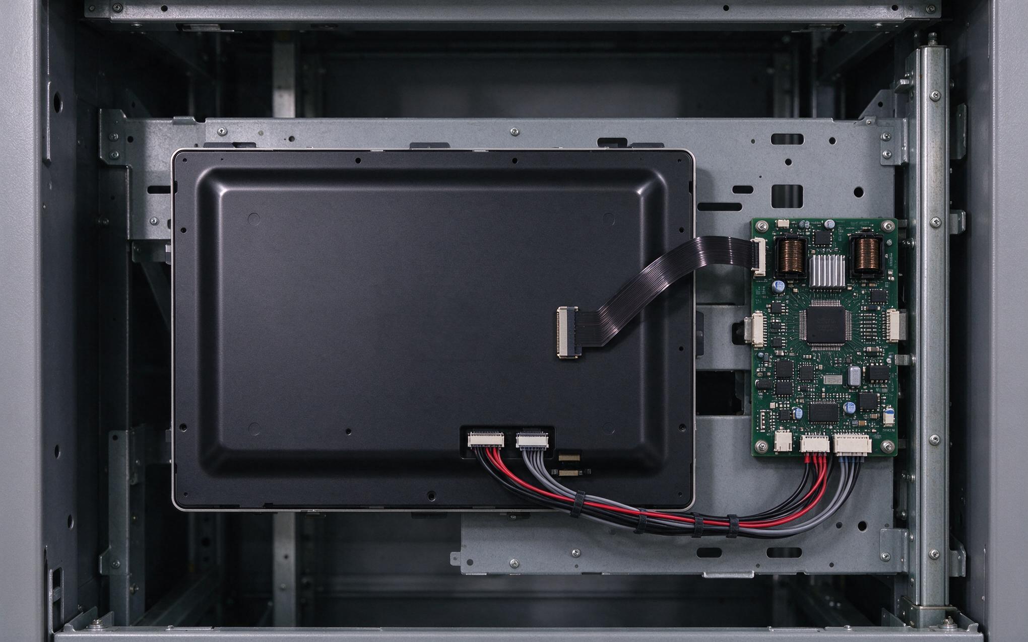
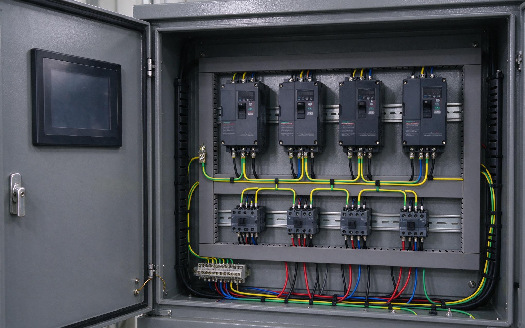
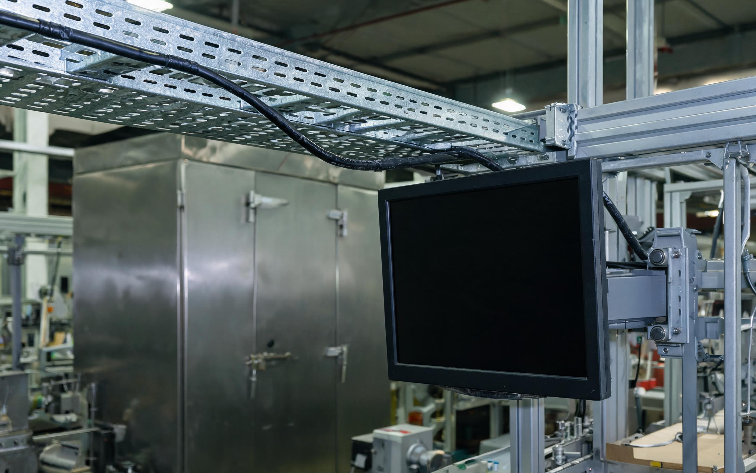
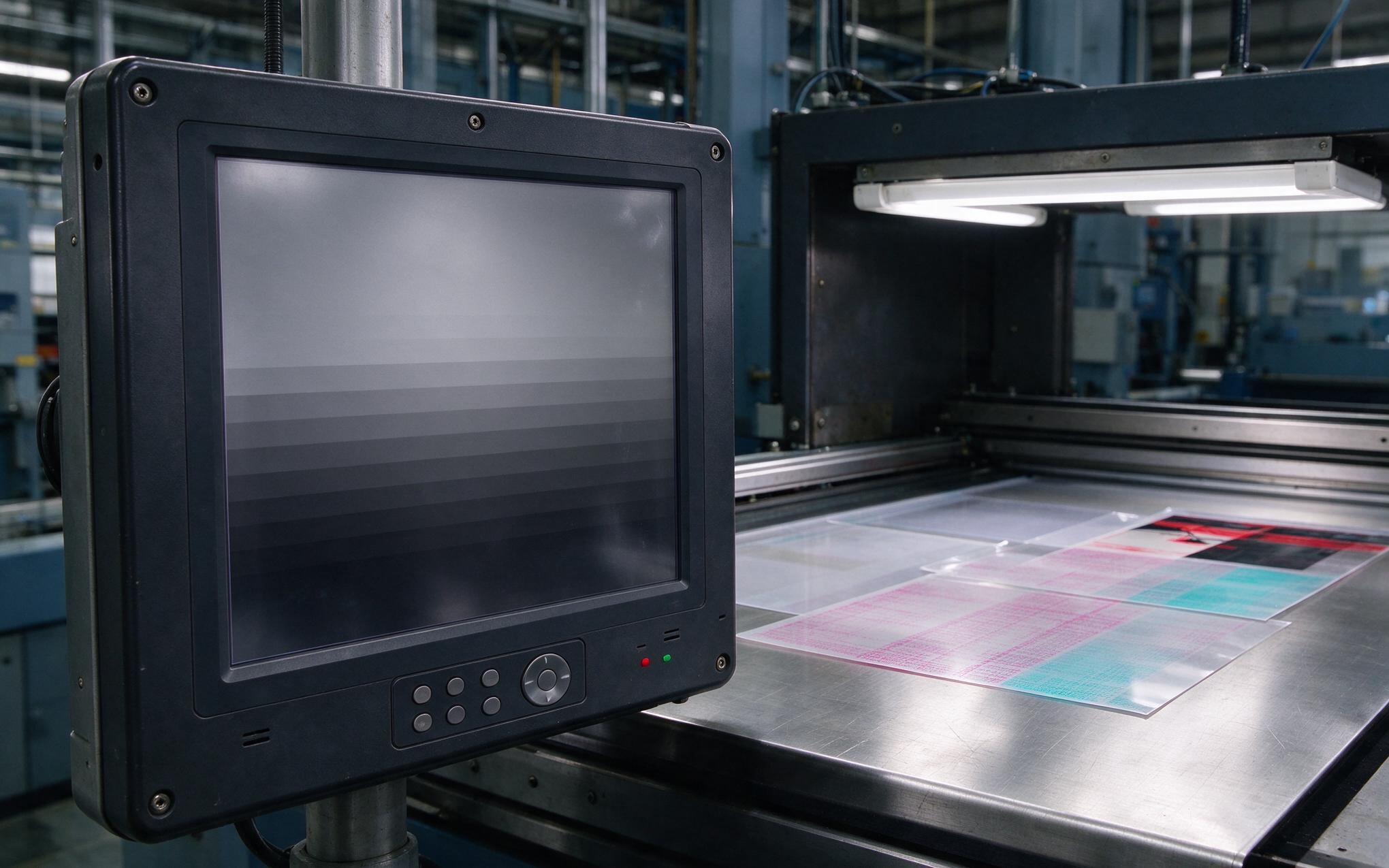
Physical cable management provides the most immediate improvement. VFD motor output cables should run in separate metallic conduit or divided cable trays from all signal and communication wiring, maintaining at least 30 centimeters of separation for unshielded runs. Where cables must cross, a 90-degree intersection minimizes the inductive coupling area. Clamp-on ferrite cores installed at both ends of the VFD motor cable absorb common-mode harmonic energy before it propagates further along the cable shield. For the display itself, selecting an industrial panel mount display with an internal metal back can and conductive gasketing around the bezel perimeter blocks radiated fields from reaching the touch sensor directly. Shielded Ethernet and serial cables with 360-degree termination at both ends complete the physical barrier. These measures address radiated and cable-borne noise without requiring changes to the drive or the display hardware.
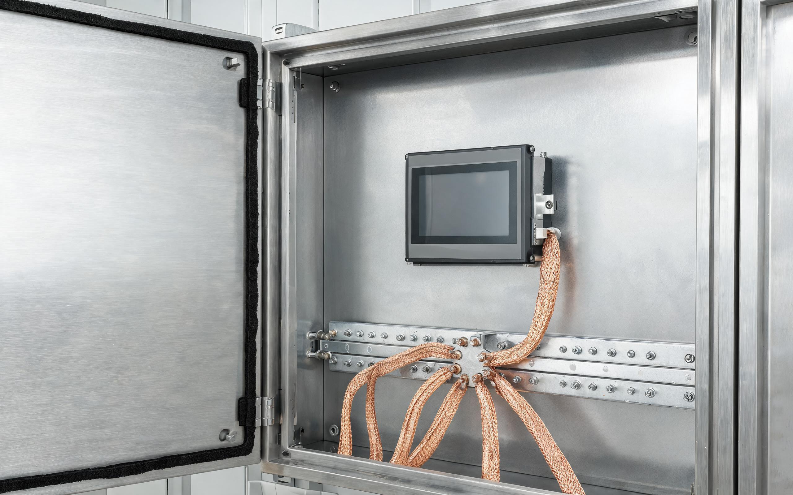
Grounding Topology and Shield Continuity in Panel Installations
Grounding architecture determines whether shielded cables actually perform as intended. A single-point equipotential bonding system, where all equipment chassis connect to a common copper ground bar through short braided straps, prevents ground loops that circulate noise currents through signal shields. Hardware designs that integrate the enclosure grounding tab directly with the internal PCB ground plane, such as the chassis bonding approach found in KOXIAN panel-mounted units, reduce the impedance between the outer shell and the circuit reference. This low-impedance path diverts coupled noise away from sensitive analog front-end circuits inside the touch controller. Separating the protective earth conductor from the signal reference at exactly one point, typically the main cabinet ground bar, avoids creating multiple return paths that convert common-mode noise into differential interference on communication lines. Field measurements consistently show that grounding improvements alone resolve over half of reported touch accuracy complaints in drive-adjacent installations.
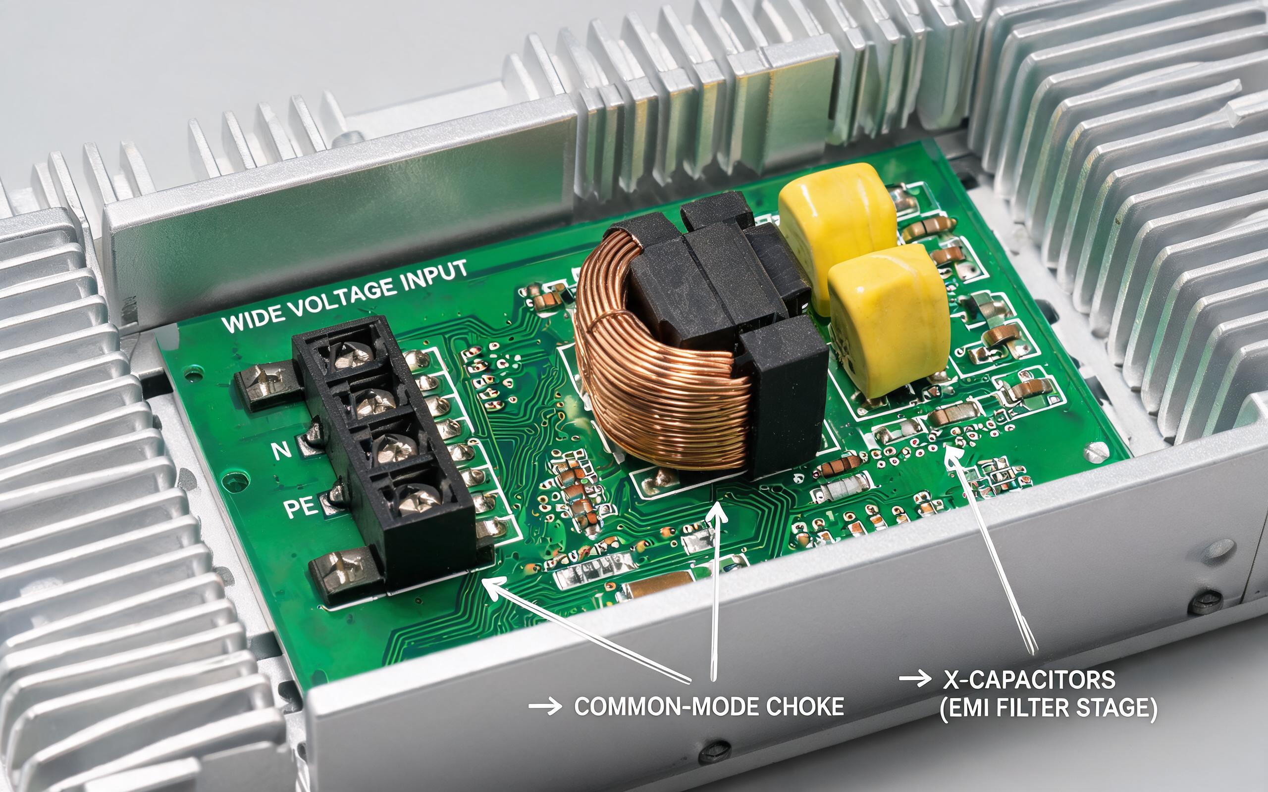
Power Input Filtering in Industrial PC Touch Screen Monitor Circuits
The power input stage represents the final conducted noise entry point. An industrial PC touch screen monitor sharing a branch circuit with VFDs receives switching transients through the AC or DC supply line. Wide-voltage input designs that incorporate common-mode chokes, X-class capacitors, and transient voltage suppressors at the inlet provide essential attenuation before noise reaches internal DC-DC converters. For installations where a rugged pc monitor operates on the same 24 VDC bus as drive control circuits, adding an isolated DC-DC converter between the bus and the display input breaks the conducted path entirely. Systems engineered with multi-stage power filtering, including designs inspired by KOXIAN power architecture that combine common-mode and differential-mode suppression stages, maintain touch controller stability even when nearby drives generate voltage spikes exceeding twice the nominal supply level.
VFD noise interference with touch screen monitors follows predictable electromagnetic coupling mechanisms that respond to systematic mitigation. Separating cable routes, applying ferrite suppression, establishing equipotential grounding, and filtering power inputs each address a specific coupling path. When these measures are implemented together rather than individually, an industrial PC touch screen monitor operates reliably even in drive-dense manufacturing environments. Procurement teams evaluating touch screen hardware for VFD-adjacent installations should verify both the shielding effectiveness of the enclosure and the filtering specifications of the power input stage.