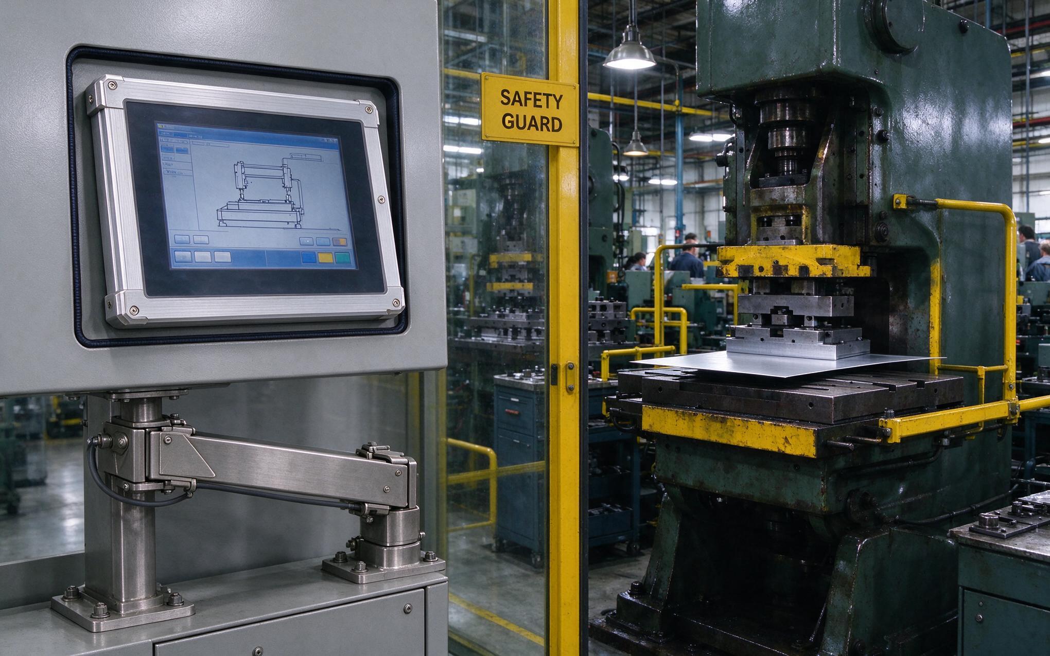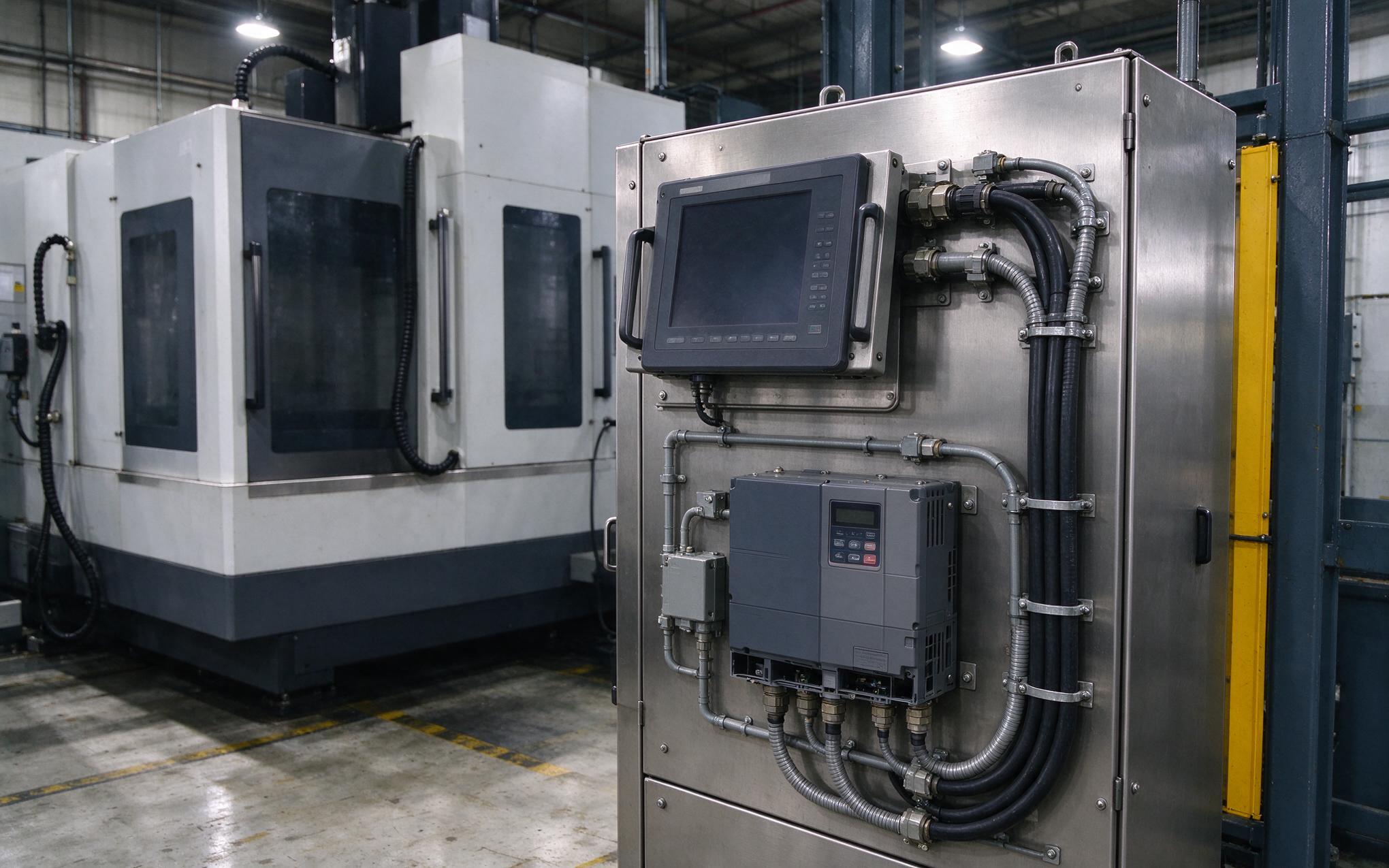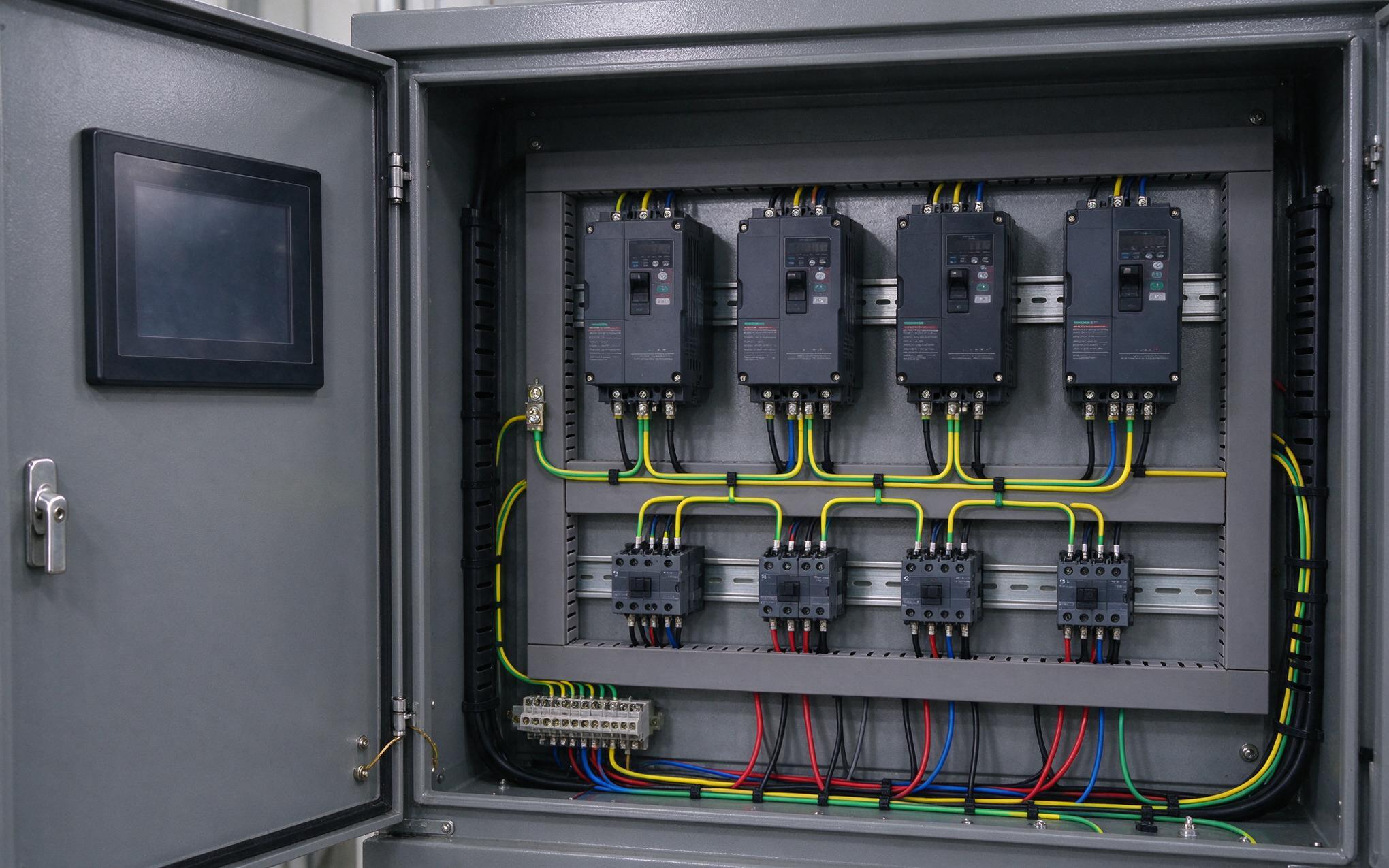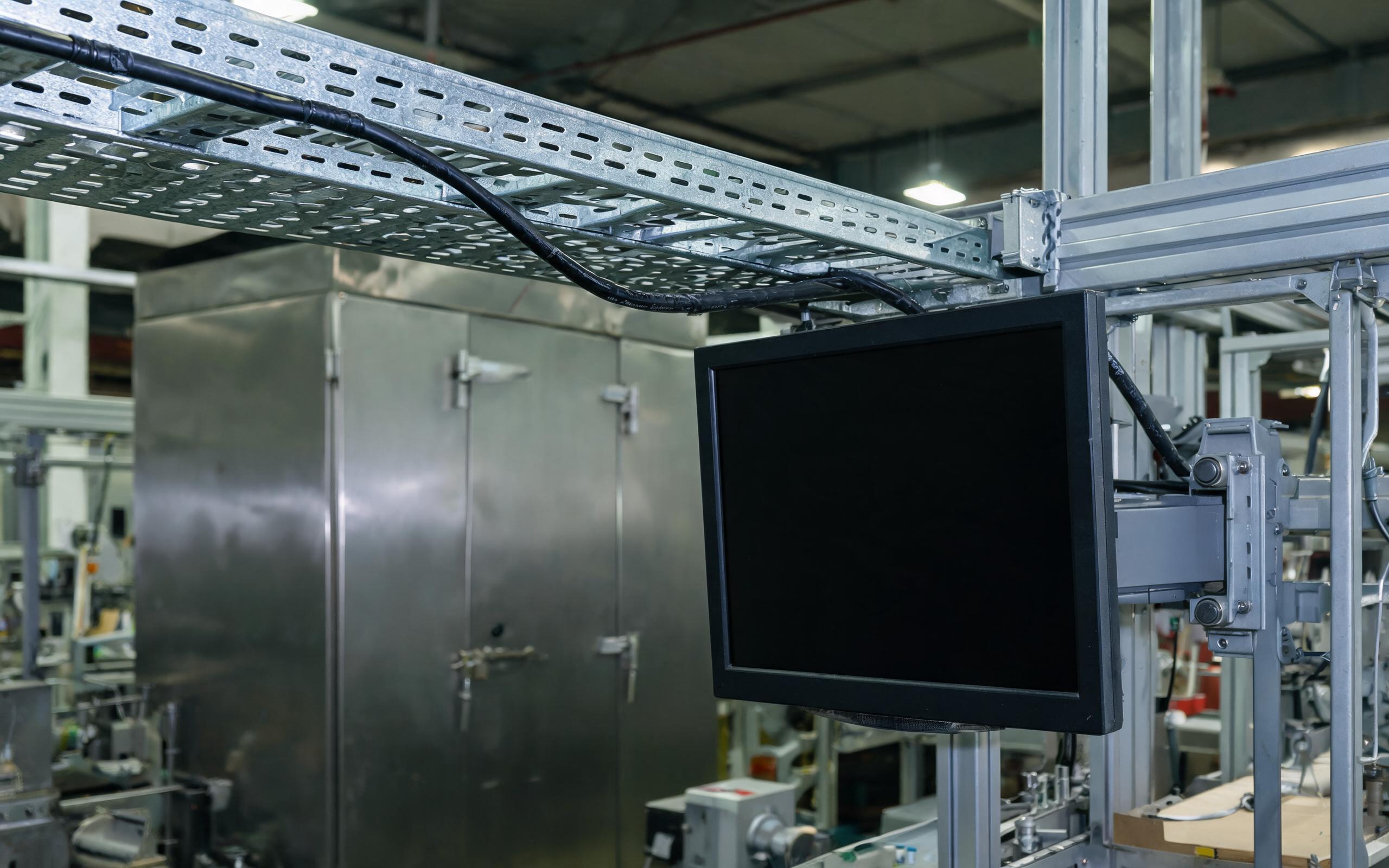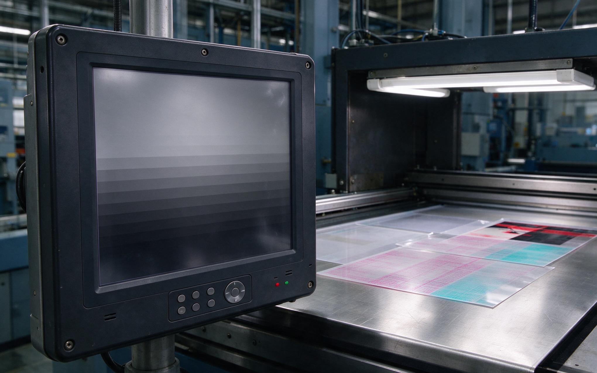
A variable-frequency drive room and a resistance weld cell sit at opposite ends of the interference spectrum. The drive room floods cabling with conducted noise and broadband switching hash from rectifiers and inverters, while the weld cell hammers nearby electronics with intense low-frequency magnetic fields and microsecond transient bursts at every electrode closure. An aluminum alloy industrial pc has to survive both, often on the same plant floor, and its enclosure does most of that work. The rules that govern material choice, seams, ventilation, and grounding change with each environment, and treating them as interchangeable is how systems end up resetting during a production run.
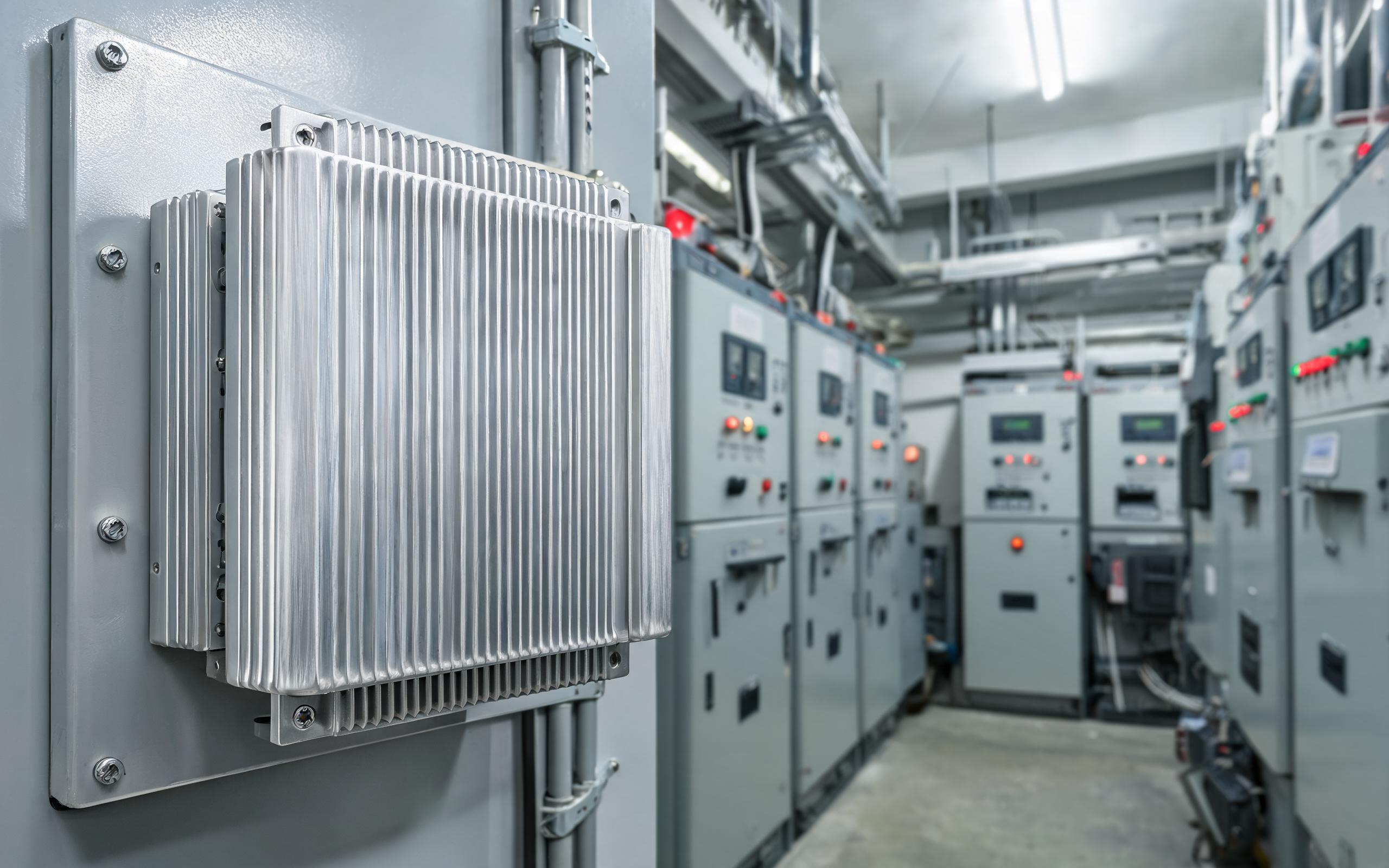
How Does an Aluminum Alloy Industrial PC Attenuate EMI?
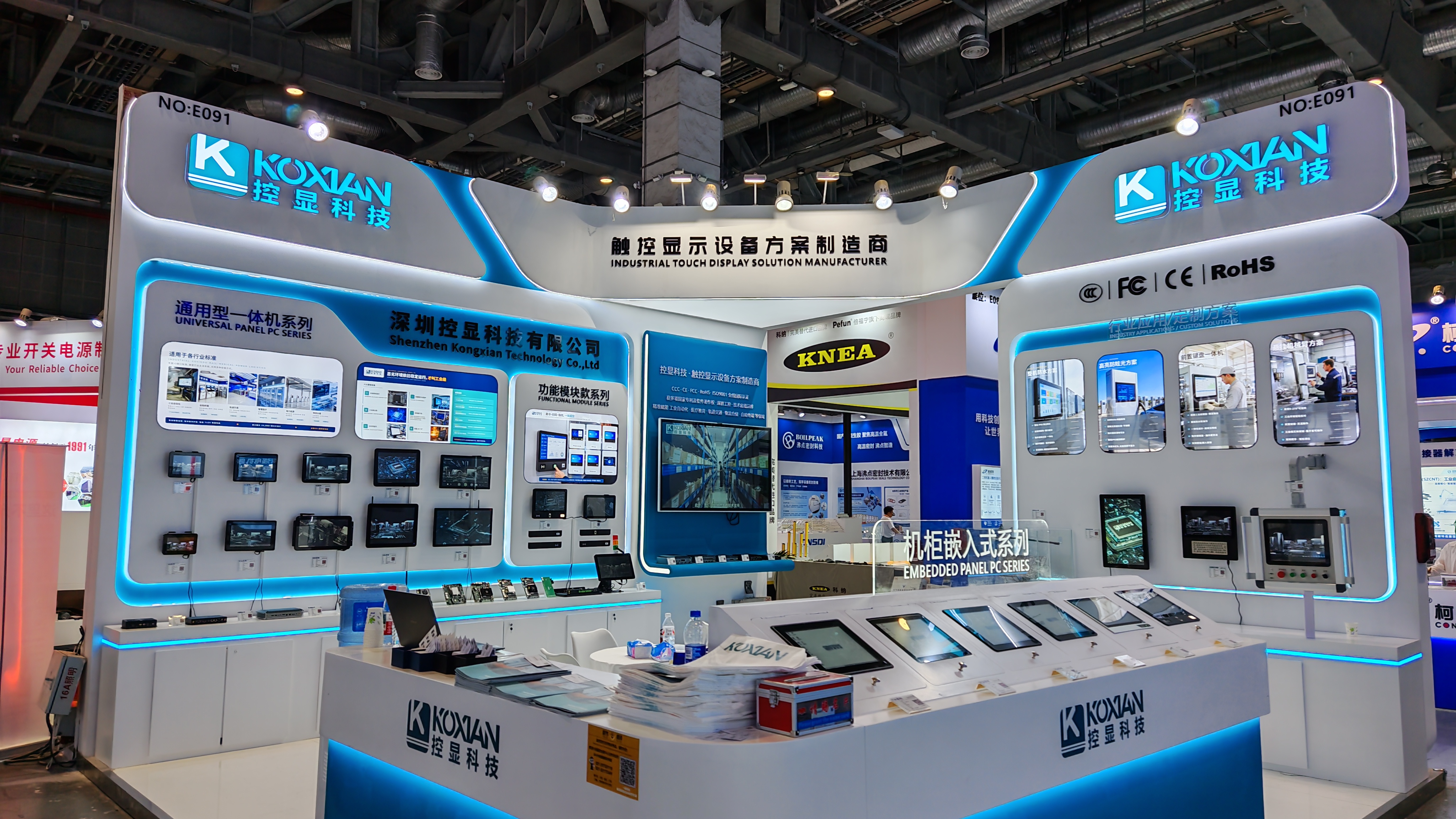
Industrial hardware manufacturers, including KOXIAN, treat the enclosure as a continuous conductive surface whose shielding comes from reflection and absorption rather than from internal coatings alone. Aluminum alloys such as 6061-T6 offer roughly twice the electrical conductivity of carbon steel, so a 2 mm wall reflects much of the incident radio energy and dissipates the rest as eddy currents, typically delivering 40 to 60 dB of shielding effectiveness across the 30 MHz to 1 GHz band where drive harmonics cluster. Weld cells attack lower, in the kilohertz magnetic range, where enclosure geometry and mass matter more than surface conductivity. The same conductive shell also contains the mainboard’s own emissions, helping the finished system meet EN 55032 radiated limits. Material choice therefore sets the ceiling for interference control before filters or layout enter the discussion.
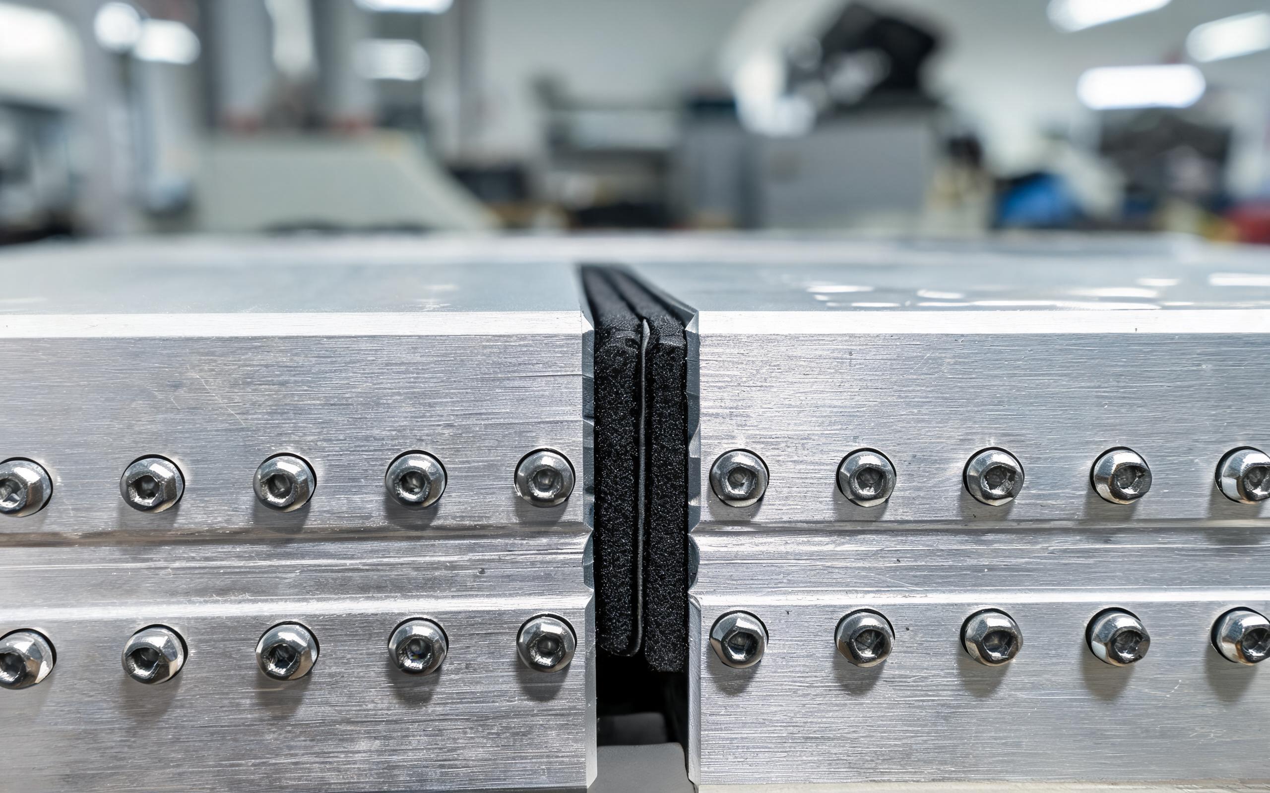
Seam Geometry and Conductive Gaskets in Chassis Design
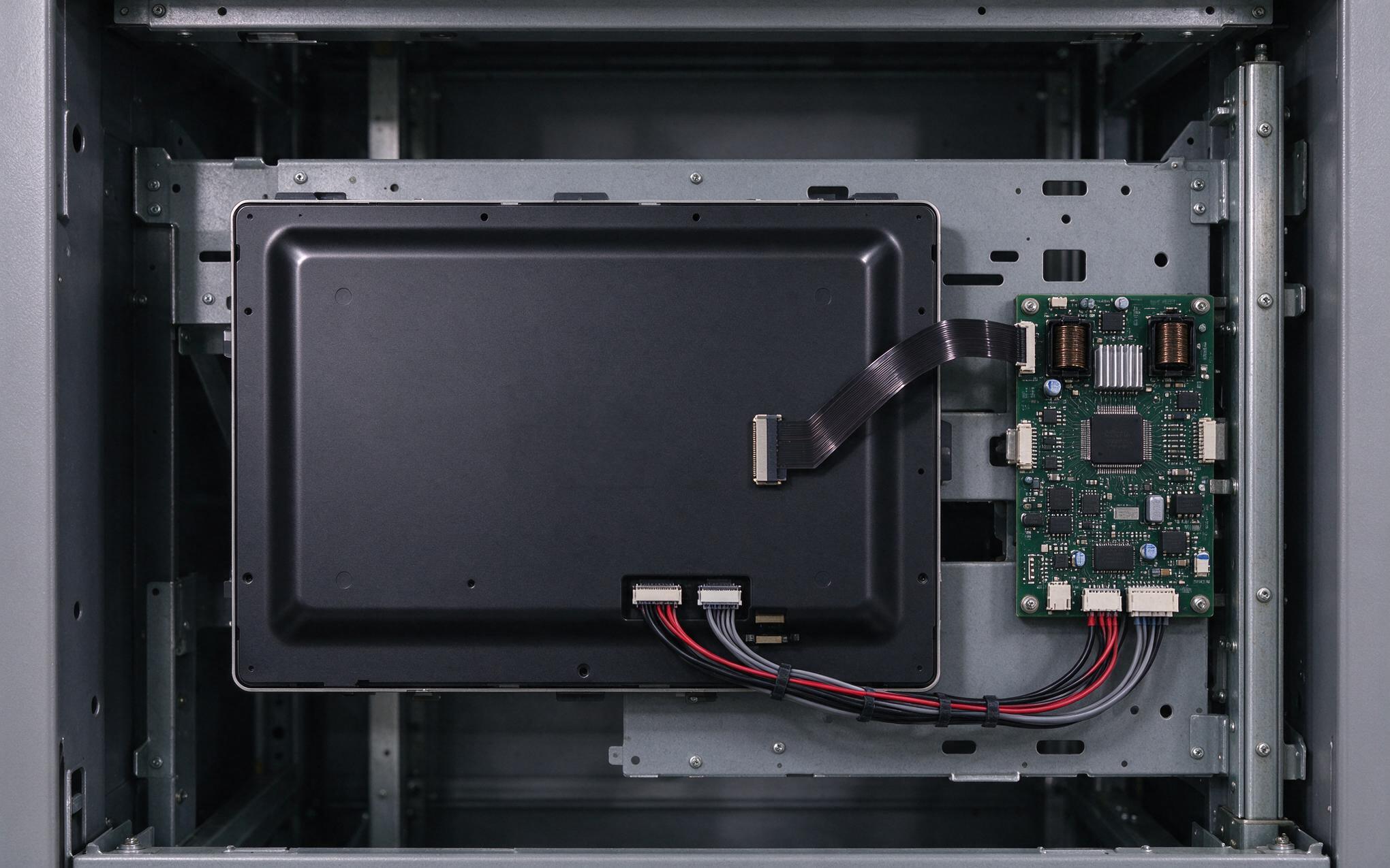
Real enclosures are assembled from panels, and every joint behaves like a slot antenna at high enough frequencies. When two machined faces meet, microscopic gaps leak energy once the wavelength approaches the gap length, so a lid that looks fully closed can still fail a radiated immunity scan in a drive room. Engineers evaluate seam flatness and structural rigidity through real-world hardware designs, such as the milled aluminum chassis implemented in the KOXIAN G1 series, where tight tolerances keep conductive gaskets compressed evenly around the full perimeter. Beryllium-copper finger stock and fabric-over-foam gaskets restore electrical continuity across joints, but only when fastener spacing and surface finish hold contact pressure uniform. Weld cells add a mechanical twist: repeated magnetic pulses flex thin panels, so gasket compression must survive vibration as well as frequency. For an aluminum alloy industrial pc, shielding integrity is always set by the leakiest discontinuity, not the average wall.
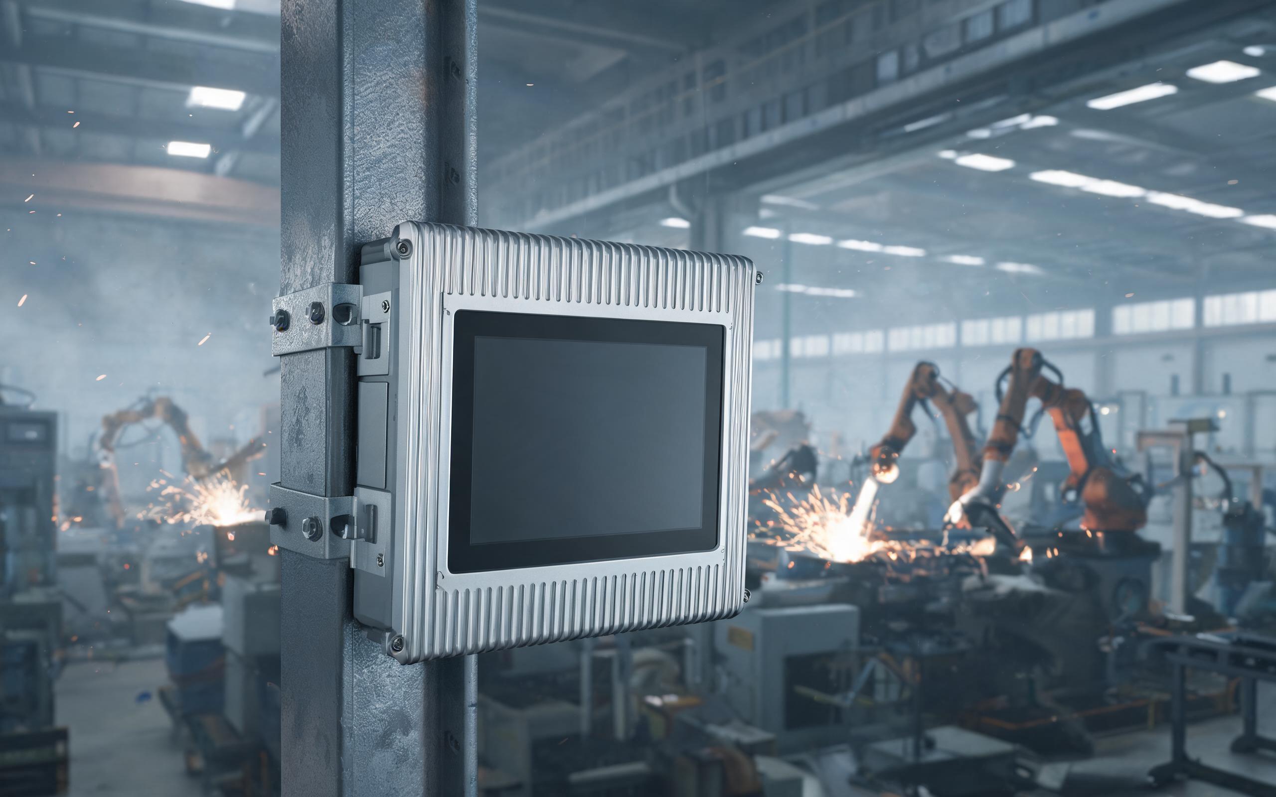
Fanless Sealing and the Ventilation Aperture Trade-Off
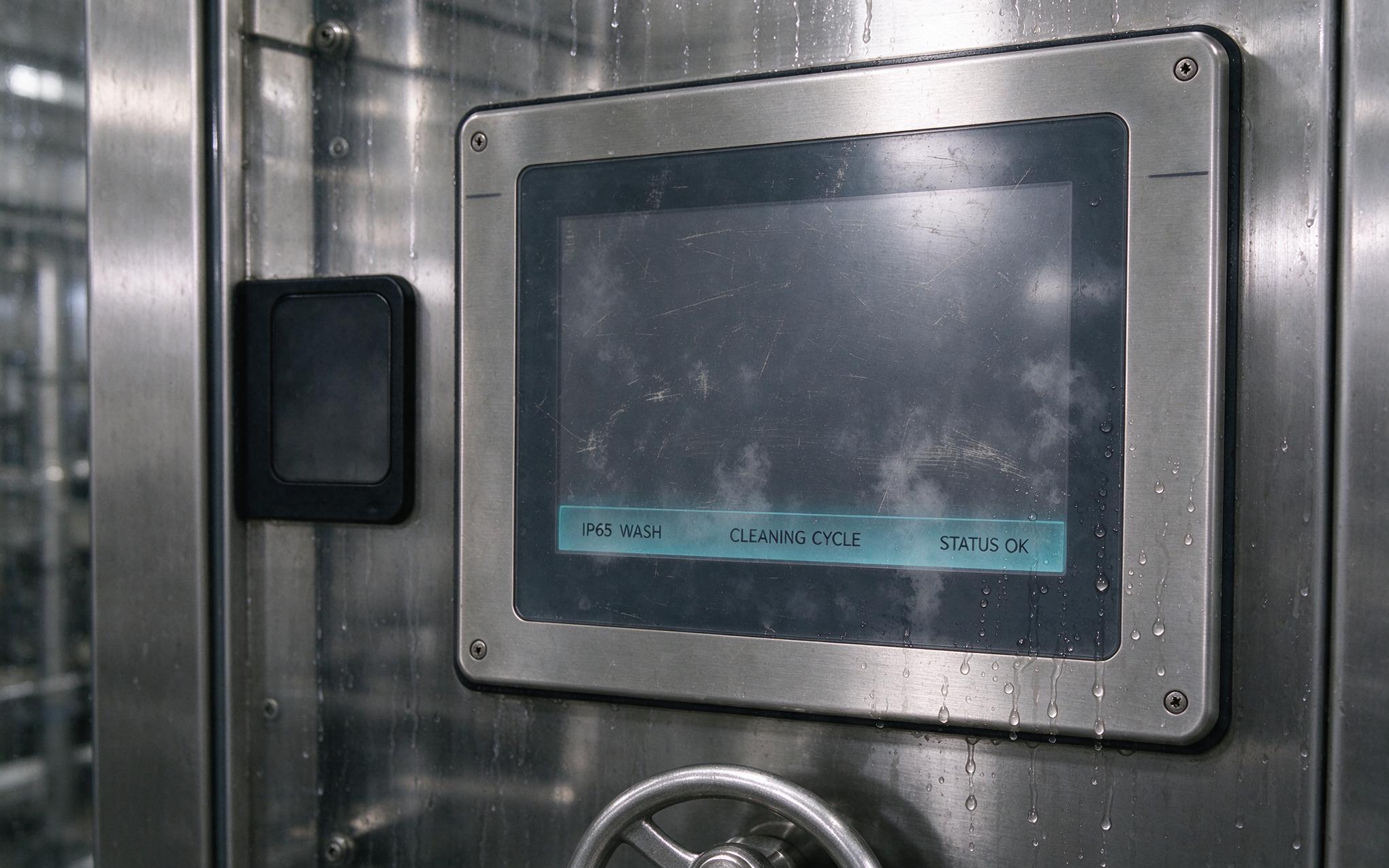
Cooling is where electromagnetic and thermal engineering collide. Every fan cutout and vent slot added for airflow becomes an aperture that leaks interference, and leakage grows with opening size until the aperture approaches resonance, which is why design rules cap any single opening near one-twentieth of the wavelength of the highest threat frequency. A fanless industrial panel pc sidesteps the problem entirely by conducting heat through the chassis itself, using finned exterior walls as the heat sink while keeping the shell closed. Where airflow cannot be eliminated, honeycomb waveguide vents provide high open area for air while attenuating radio energy below their cutoff frequency. This dual role explains why the aluminum alloy industrial pc dominates sealed designs: the alloy moves heat roughly four times faster than carbon steel, so one structure serves as both Faraday cage and thermal path.
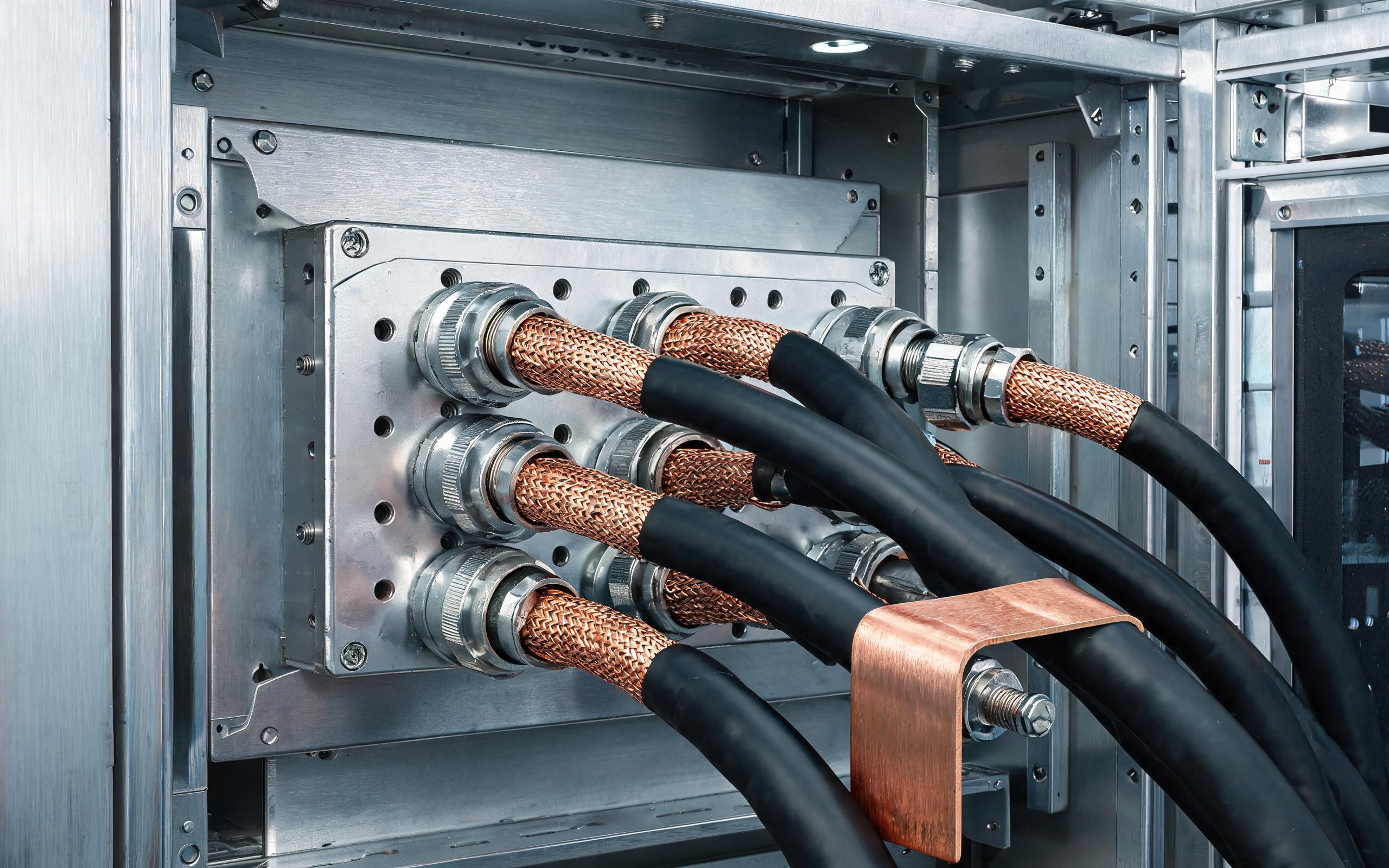
Grounding and Cable Entry Discipline During Installation
Even a well-designed chassis fails when installation practice breaks its continuity. Anodized aluminum is electrically insulating, so mating panels need conductive treatment such as chromate conversion at contact zones; field measurements put untreated joints at tens of ohms, while treated joints drop below 0.1 ohm and keep high-frequency currents flowing on the enclosure surface where they belong. For an embedded industrial pc sharing a cabinet with drive rectifiers, cable entries deserve equal attention: shielded cables should bond to the connector shell across the full 360 degrees rather than through a pigtail, and filtered connectors strip noise before it reaches the board. To contain surges riding in from long weld-cell wiring runs, embedded computing setups inspired by KOXIAN power architecture pair filtered I/O with low-impedance chassis bonding at the entry point.
The drive room and the weld cell punish different weaknesses, so the rules differ: conductivity and seam discipline carry the drive room, while mass, compression stability, and bonding carry the weld cell. The aluminum alloy industrial pc earns its place in both because the enclosure can be engineered as a continuous, conductive, sealed structure rather than a decorative box. Specifying teams that ask about shielding effectiveness, gasket strategy, aperture limits, and bonding impedance will deploy hardware that survives either environment without mysterious resets.