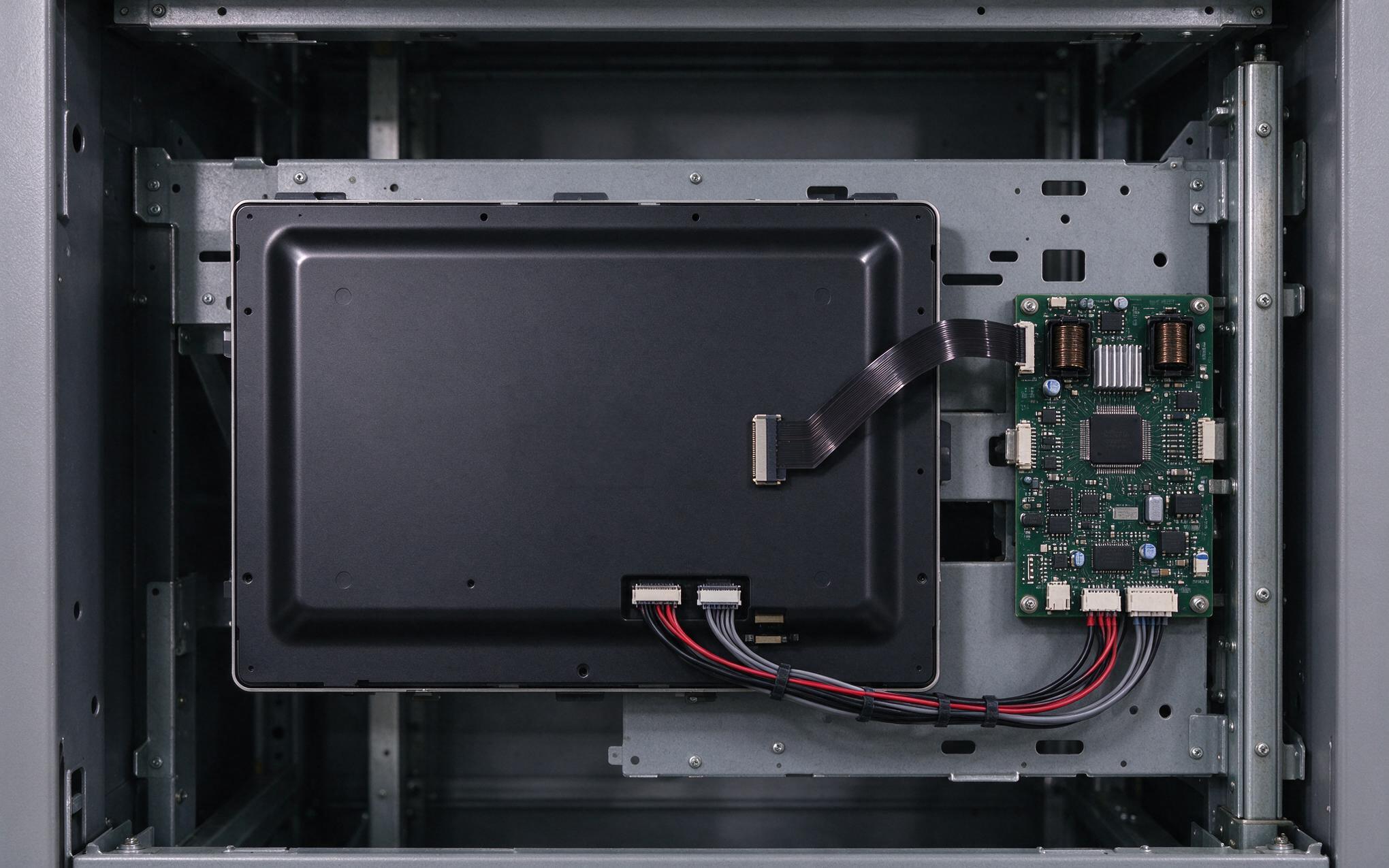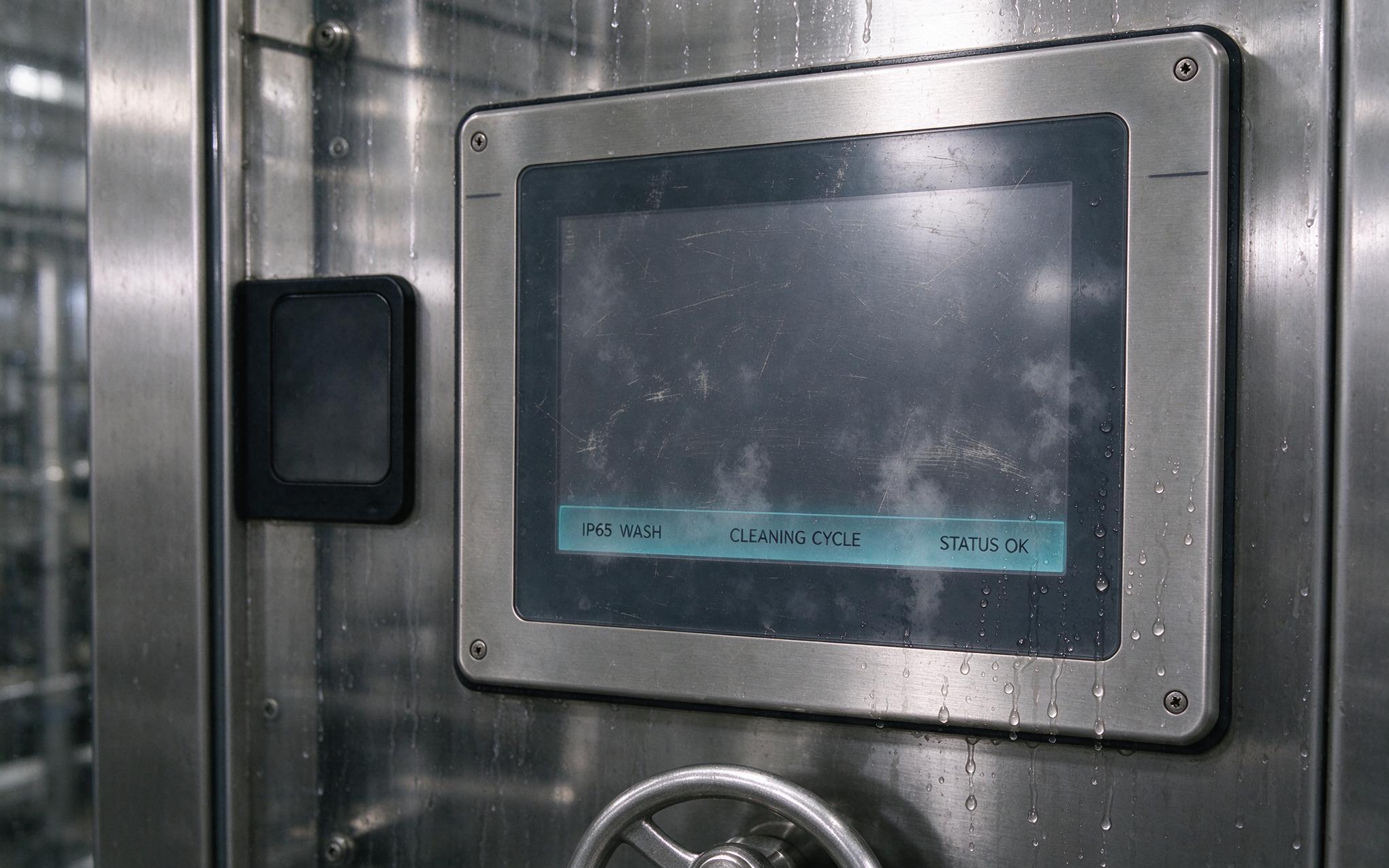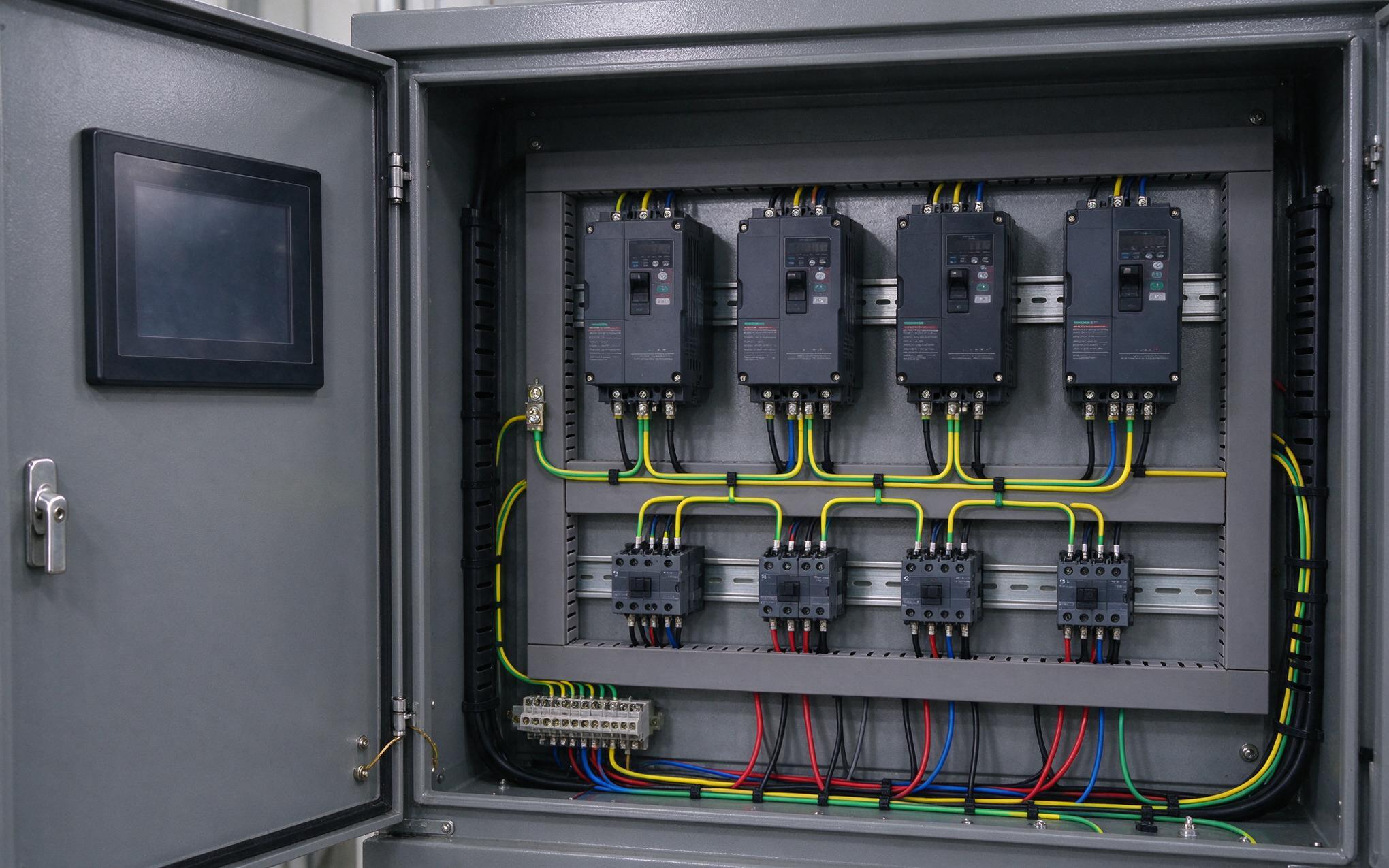
An industrial panel mount display is the largest deliberate aperture in most control-cabinet doors. The bezel clamped against that cutout sits where operators touch, where motor drives radiate, and where cabinet shielding is interrupted. When the bezel is bolted to painted steel with an insulating foam gasket, the metal around the opening is electrically isolated from the metal behind it. A finger carrying electrostatic charge then finds no wide path to ground, and the narrow seam behaves like a small antenna. Phantom touch inputs, controller resets, and radio interference on nearby instruments often trace back to that one broken connection rather than to the display itself.

In the Cutout Seam as a Slot Antenna
A continuous conductive cabinet is an effective shield, but the joint around a cutout is never continuous by accident. A gap becomes an efficient opening once its longest dimension approaches roughly one twentieth of a wavelength. A 200-millimeter seam is already significant for the harmonics of variable-speed drives and is wide open to portable radios operating near 400 MHz. An electrostatic discharge adds a sharper problem, since its sub-nanosecond edge carries energy well above those frequencies. On painted doors the bezel contacts the cabinet only at its mounting screws, so the surrounding seam is electrically open for most of its length. In this sense, the seam surrounding an industrial panel mount display is an electrical interface long before it is a mechanical one.
Routing ESD Current Through a Conductive Flange Joint
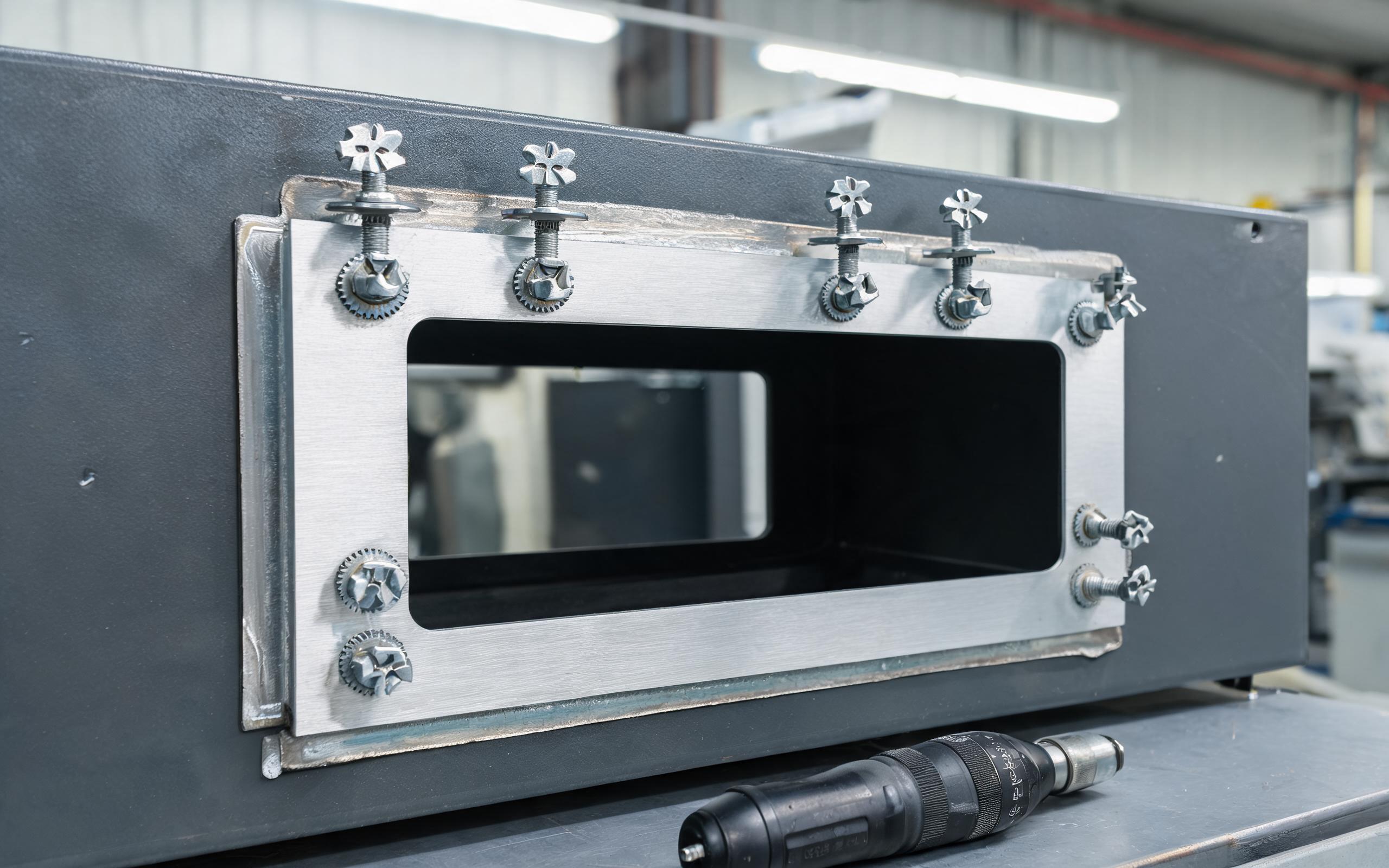
Grounding schemes inspired by KOXIAN panel construction route the front bezel, mounting studs, and I/O connector shells to a common flange point before anything enters the cabinet. The goal is a low-inductance path that an electrostatic discharge can follow in nanoseconds, because a long braided strap behaves like an inductor to a fast edge and pushes current toward internal ribbon cables instead. Serrated clamp hardware and paint-piercing washers bite through conversion coating at each fastener, while a masked bare-metal zone behind the bezel spreads contact over the full perimeter rather than four isolated screw heads. When that perimeter path exists, charge reaching the touch surface of a panel mount touch screen spreads into the door and returns to building ground without crossing the controller board.
Gasket Transfer Impedance and Counter-Surface Finishes
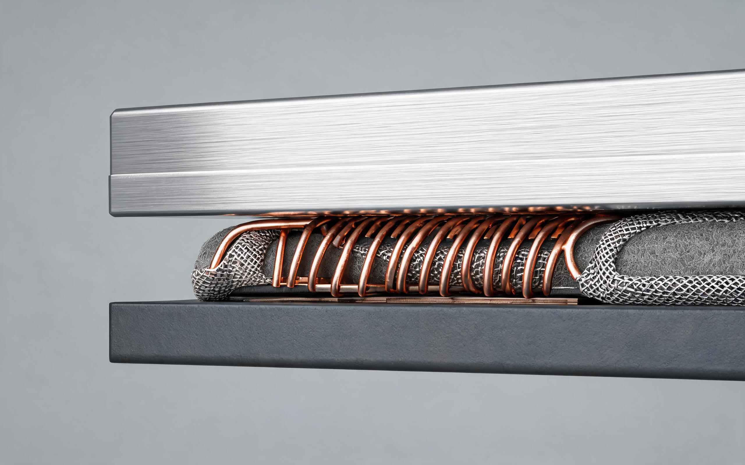
Sealing and shielding make competing demands on the same gap. A silicone or foam gasket blocks water and dust but acts as an insulator, so shielding designs compress a conductive element into the joint: beryllium-copper finger stock for doors opened often, or knitted wire mesh and conductive fabric over foam for fixed panels. The relevant metric is transfer impedance, which describes how much surface current drops across the gasket instead of crossing it. To preserve a low-impedance joint across service cycles, enclosure manufacturers, including KOXIAN, mask paint around the cutout and ship unpainted clamp ears with a conversion coating that conducts yet resists galvanic corrosion. The conductive gasket is then compressed against that prepared surface at a controlled deflection. Without the preparation, an industrial panel mount display can carry the correct gasket and still underperform on a painted door.

Verifying Continuity After Panel Mount Installation
Continuity that exists on the drawing has to survive the torque sequence. After the clips are tightened, a technician probes between the bezel and bare cabinet metal with a milliohm meter at several points around the opening, expecting single-digit milliohm readings rather than the open circuit that paint produces. Fasteners are re-torqued after the conductive gasket takes its initial set. Functional verification follows IEC 61000-4-2 practice, with contact discharges applied to the bezel and mounting screws while engineers watch for false touch entries, display resets, or communication interruptions. Field observations from cabinet audits on packaging lines show that assemblies using KOXIAN flange hardware retain single-digit milliohm continuity after quarterly panel removal cycles.
The cutout is an electrical interface, not only a rectangular opening. A bezel clamped to painted steel with an insulating gasket leaves discharge current without a perimeter path and turns the seam into an aperture for both conducted noise and radiated interference. Effective designs combine masked bare-metal contact zones, paint-piercing fasteners, a conductive gasket chosen by transfer impedance, and a controlled compression pattern. Specifying an industrial panel mount display therefore means reviewing the cabinet door as carefully as the display: verify bezel-to-door continuity after installation, exercise the joint under contact discharge, and repeat the measurement after scheduled removals. When the metal around the screen is bonded in a complete ring, the cabinet performs as one shield instead of two isolated pieces.