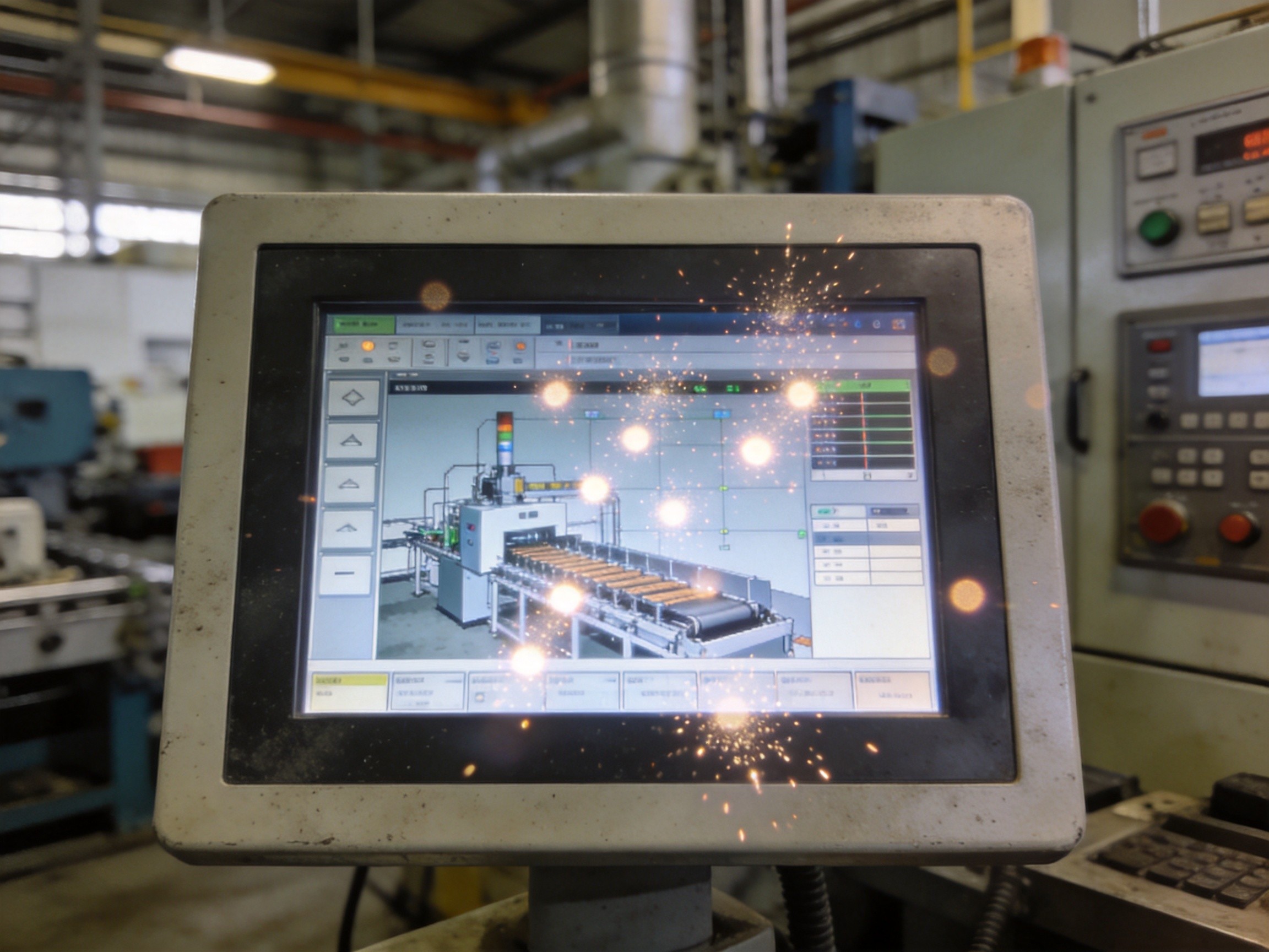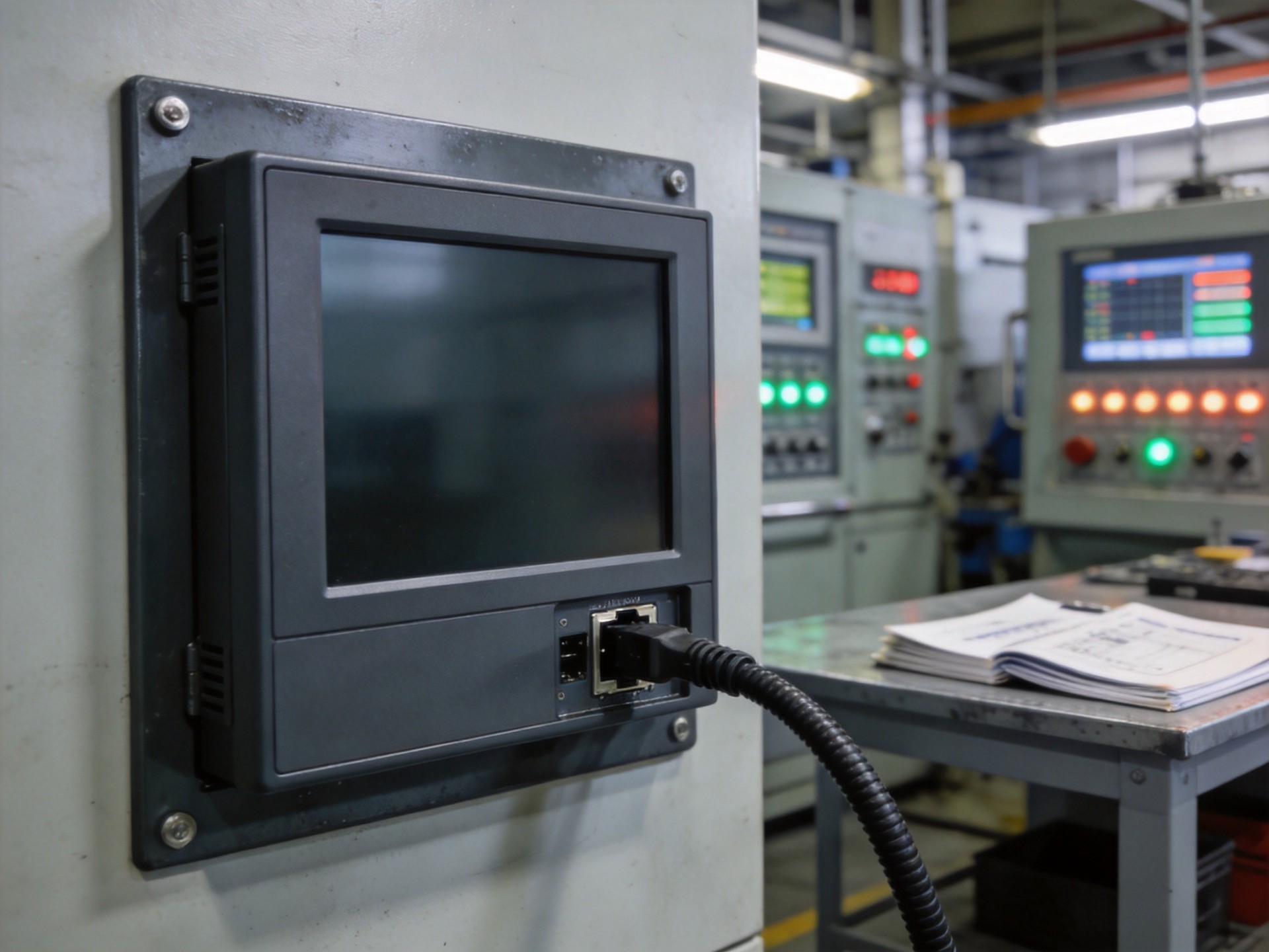
Ground loops are among the most persistent failure modes in industrial touchscreen deployments. The symptoms are easy to recognize: erratic cursor jumps, ghost touches that register without physical contact, complete unresponsiveness that appears and disappears unpredictably, or a slow drift in touch coordinate accuracy that worsens over hours. The underlying cause is less obvious. Ground loop noise infiltrates the touch controller’s analog front end through potential differences between the chassis ground of the panel PC and the electrical ground of the machine it is mounted to. When these ground potentials differ by even a few hundred millivolts, the resulting current flow through the touch sensor’s reference plane creates noise that the controller’s signal processing chain must contend with — and often loses to.
The Physics of the Problem
A ground loop forms when two or more points nominally at ground potential connect through both a signal path and a power path, creating a conductive loop. In a typical panel PC installation, the display assembly mounts to a steel support arm bonded to the facility’s protective earth, while the panel PC receives DC power from a supply referencing a different ground point — perhaps a control cabinet on the opposite side of the production cell. The voltage difference between these two references, even at 50 millivolts, drives current through the loop. The touch controller sits directly in this path because its sensor — a transparent conductive layer laminated to the display glass — is capacitively coupled to the chassis. The 50 or 60 Hz line frequency, along with harmonics from variable frequency drives and switching power supplies, modulates this ground current. The resulting noise spectrum overlaps directly with the excitation frequencies the touch controller uses to detect finger position.
Diagnosis: Separating Ground Noise from Other Failure Modes
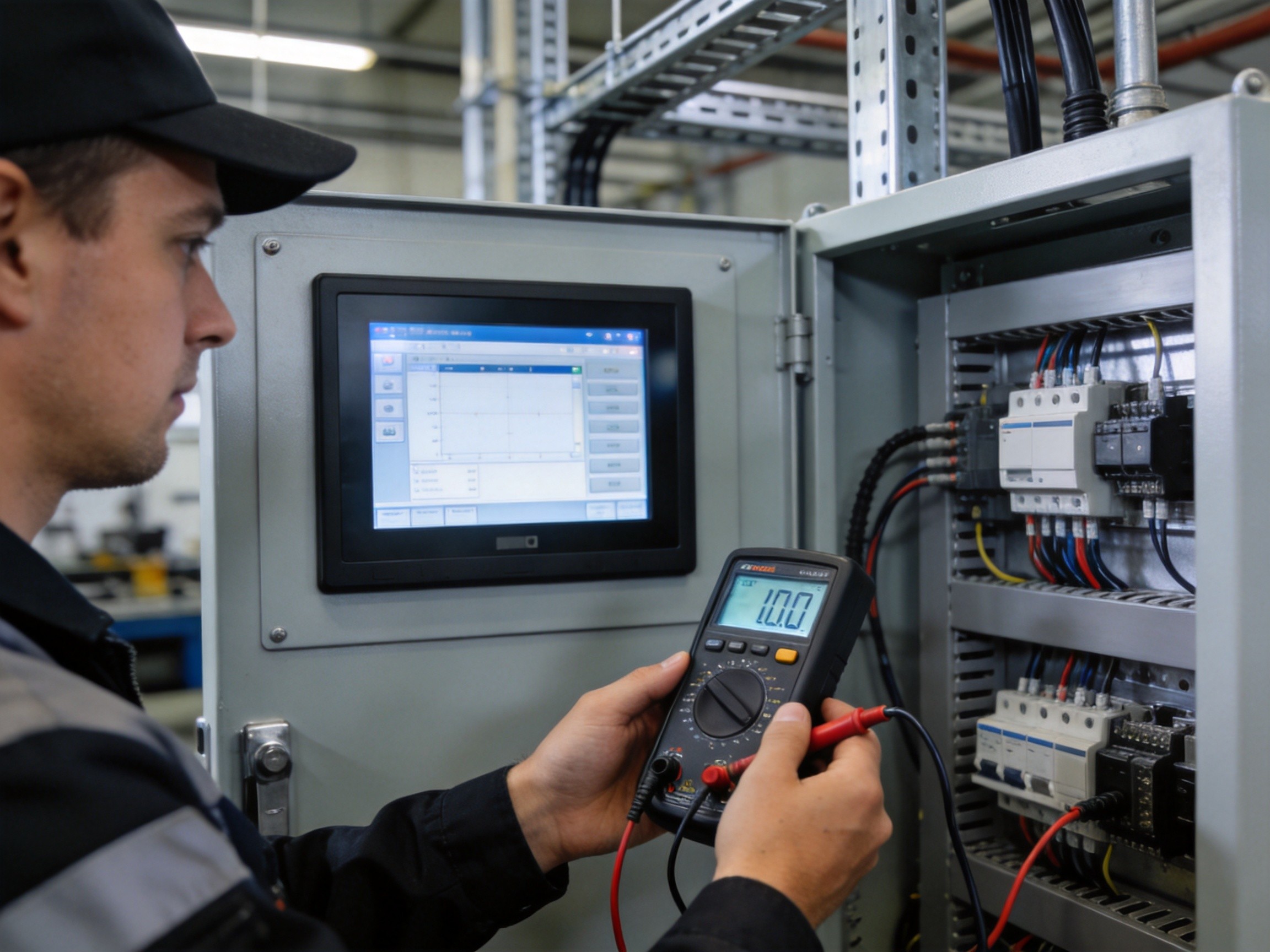
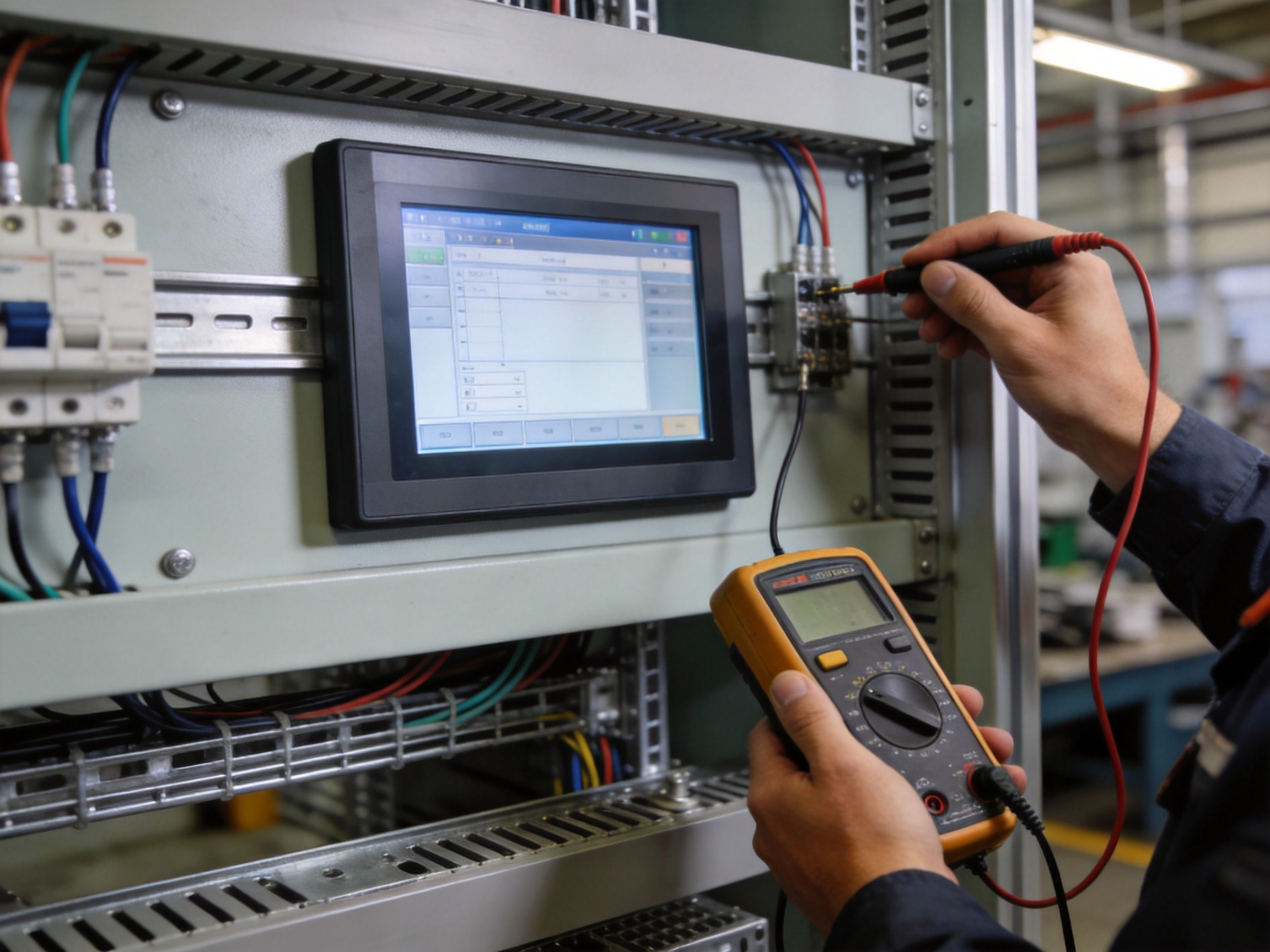
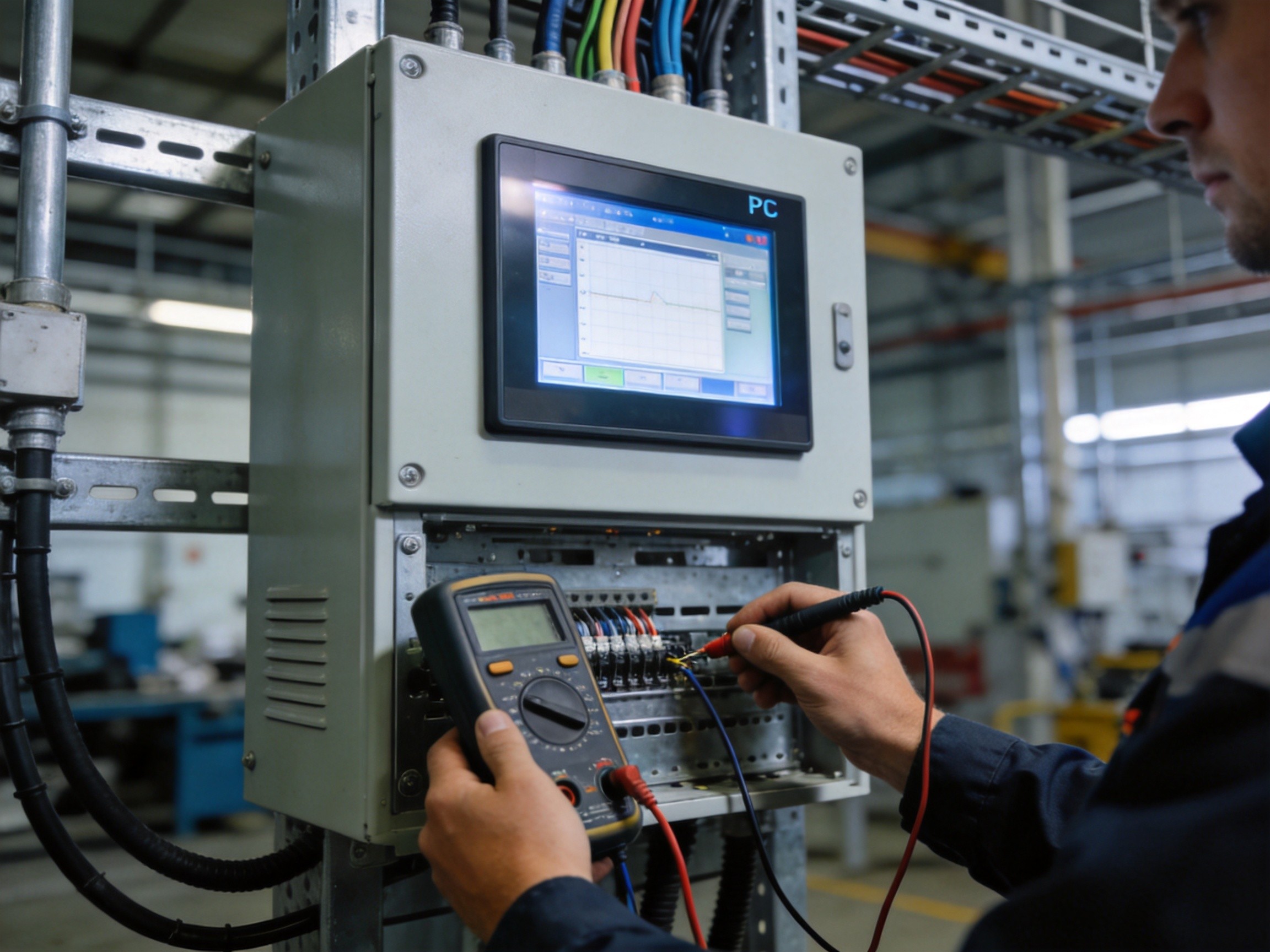
The first step in resolving erratic touch behavior is confirming that ground loop noise is the actual cause. Touch failures can also originate from damaged flex cables, delaminated touch sensors, driver conflicts, or EMI from nearby equipment. The definitive diagnostic test is to temporarily isolate the panel PC chassis from its mounting structure using a non-conductive barrier — a sheet of rigid plastic or dry wood — and observe whether touch behavior returns to normal. If it does, the ground loop is confirmed. A multimeter in AC millivolt mode between the chassis and mounting point provides a more precise measurement: readings above 100 millivolts AC strongly indicate a ground loop. A spectrum analyzer on the touch controller’s reference line will show distinct peaks at the line frequency and its harmonics, distinguishing this from the broadband noise of radiated EMI.
The Fix Hierarchy: From Simple to Structural
Ground loop remediation follows a clear escalation path. The simplest fix is ensuring the panel PC and the equipment share a single, low-impedance ground reference — running a dedicated grounding conductor, typically 10 AWG or heavier, from the panel PC chassis grounding lug to the same ground bus the machine frame references. If a shared ground is impractical, a galvanic isolator on the touch controller’s communication interface rated for 1,500 volts or higher breaks the ground loop while passing data transparently. KOXIAN offers panel PC configurations with isolated touch controller modules for installations where external isolators are not viable. The least desirable approach is floating the panel PC chassis entirely with non-conductive bushings — a last resort that compromises the safety ground path and may violate electrical codes.
Prevention at the Specification Stage
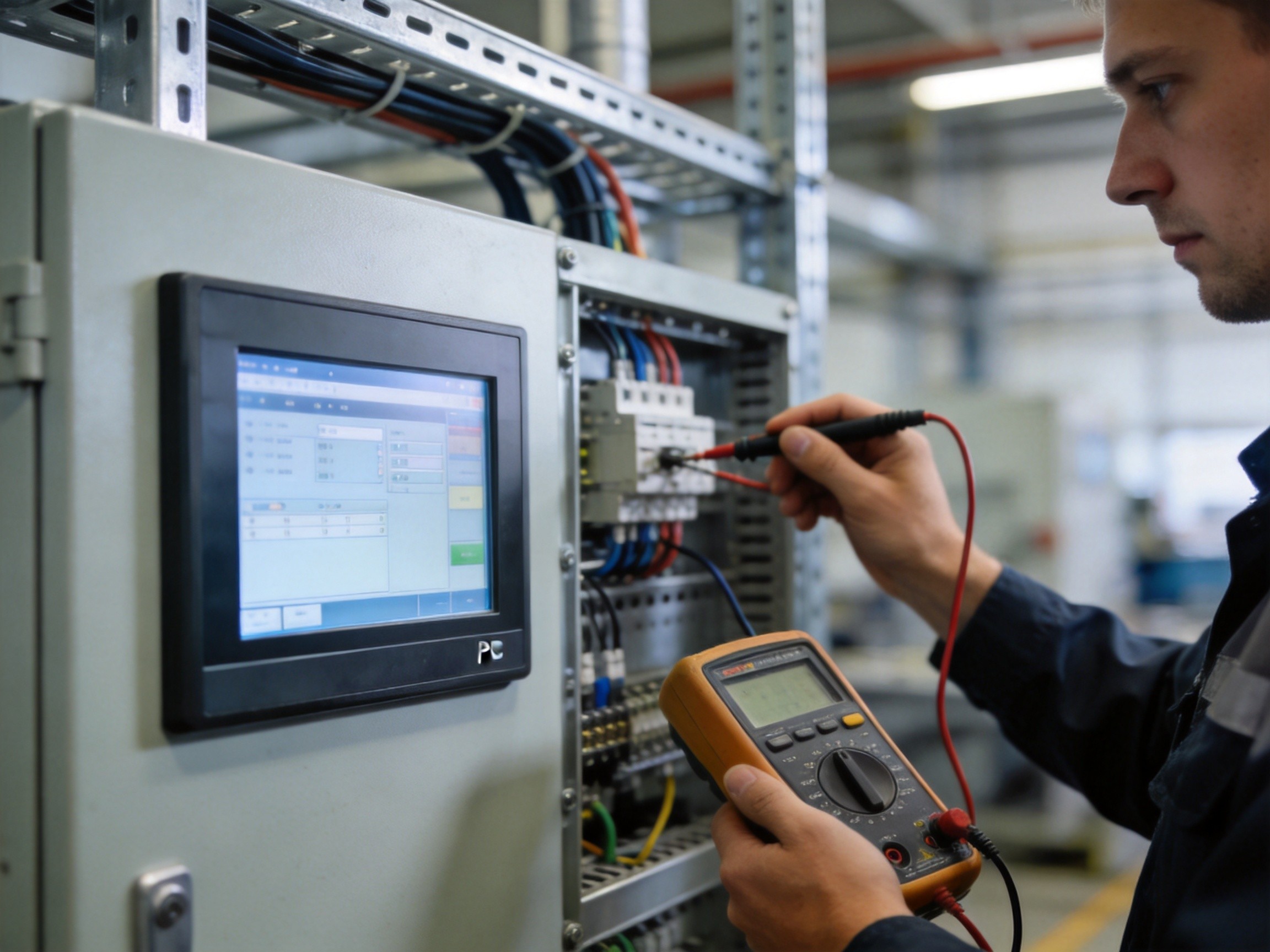
The most cost-effective approach to ground loop problems is preventing them during system design. Touch controllers with high common-mode rejection ratios — 80 dB or better — resist ground noise more effectively. Differential signaling on the touch sensor interface, rather than single-ended, provides additional immunity. During installation, contractors should verify that the ground potential difference between the panel PC mounting location and the nearest equipment ground bus is below 50 millivolts AC before powering on. This single measurement, performed during commissioning, prevents weeks of intermittent touch failures that would otherwise be misdiagnosed as software bugs. The cost of a five-minute ground verification is negligible compared to the production downtime and unnecessary hardware replacements that follow from unresolved ground loop noise.
Ground loop noise is not a manufacturing defect — it is a system integration challenge that arises from connecting sensitive analog electronics to large metal structures in electrically noisy industrial environments. The solution demands a disciplined approach to grounding architecture, diagnostic verification, and component selection. KOXIAN addresses this at the design level by incorporating high-CMRR touch controllers and offering isolated interface options in its panel PC lineup, though the most critical factor remains proper site grounding. When a panel PC touchscreen behaves erratically, the first tool to reach for is a multimeter, not a replacement unit. The most reliable touch interface cannot function correctly when its reference plane carries current it was never designed to handle.