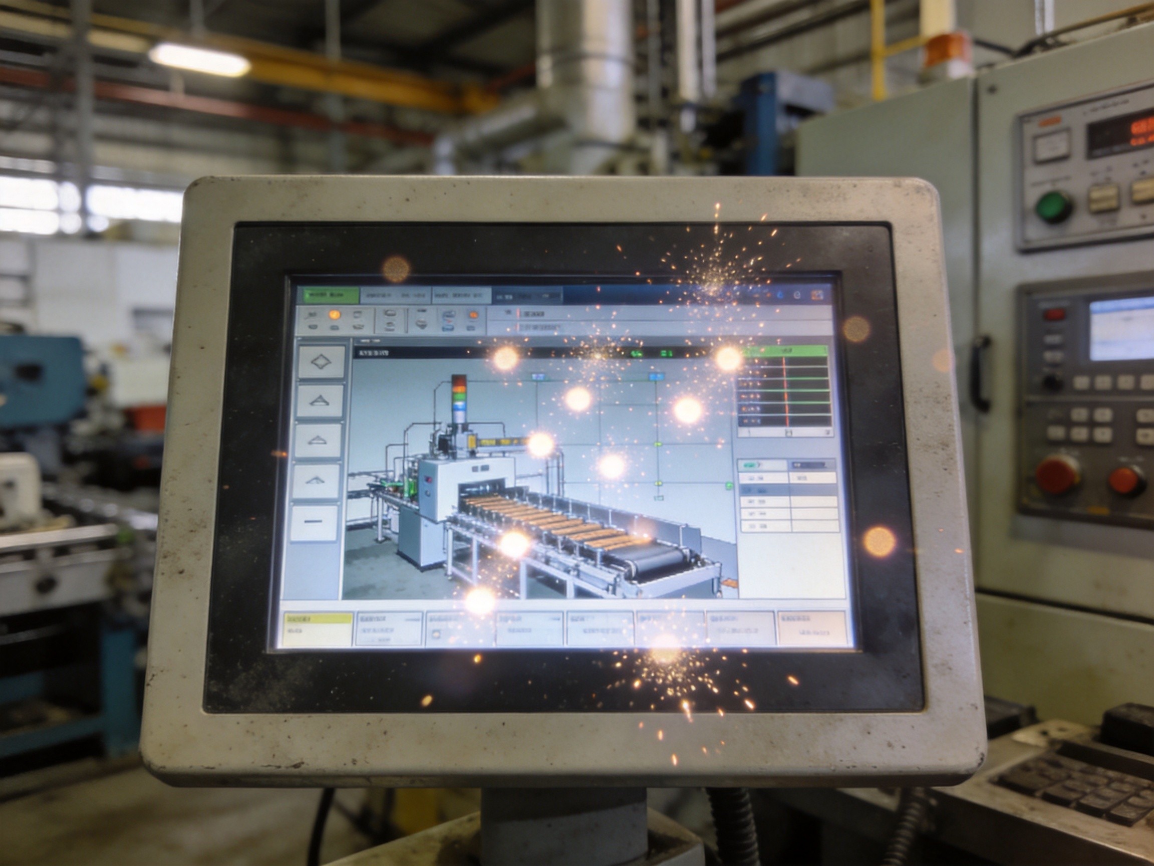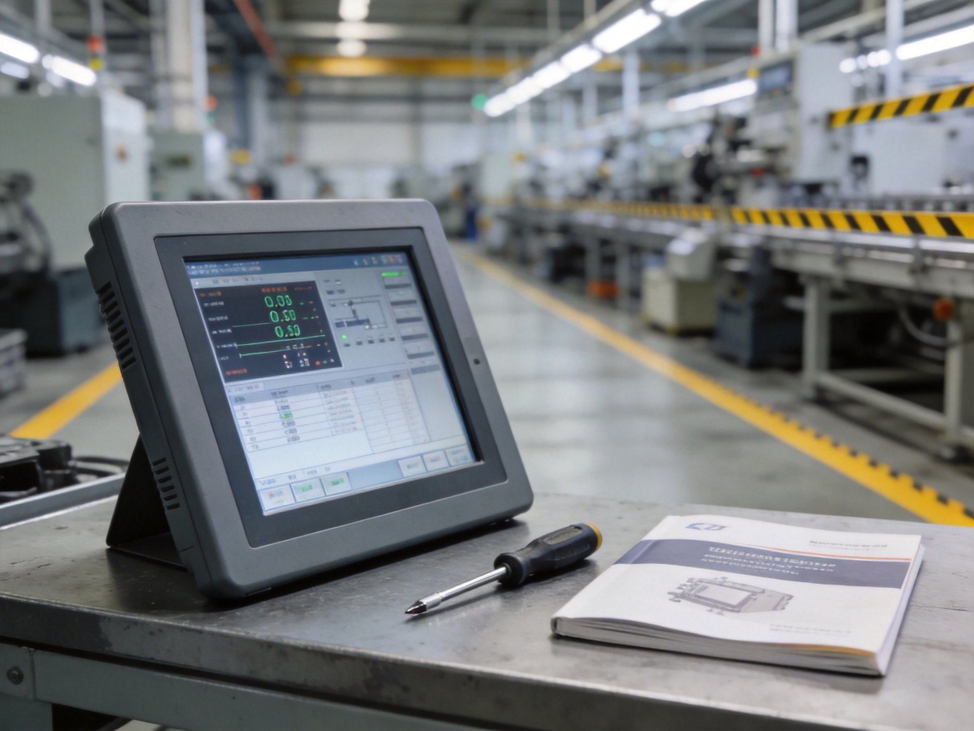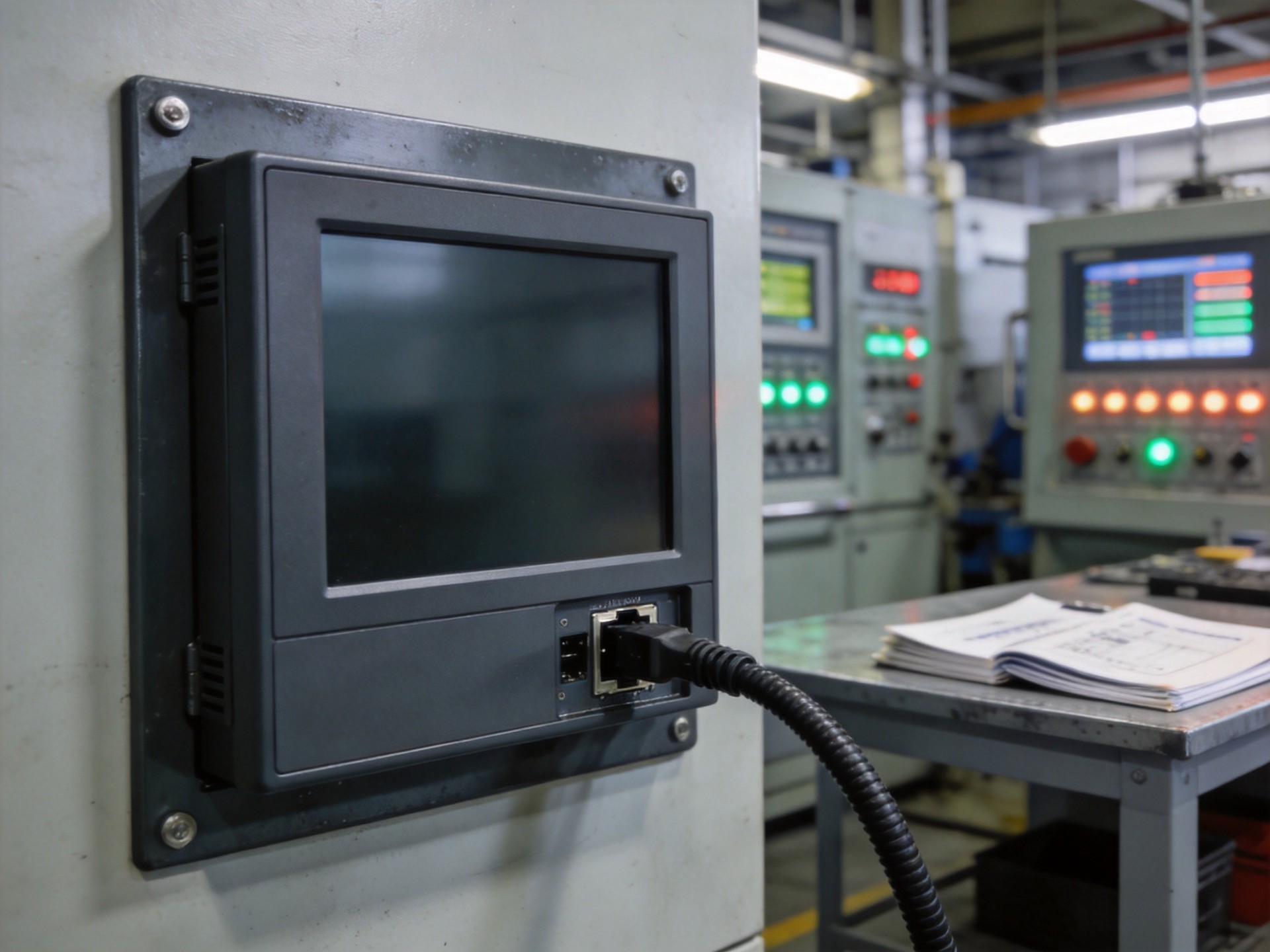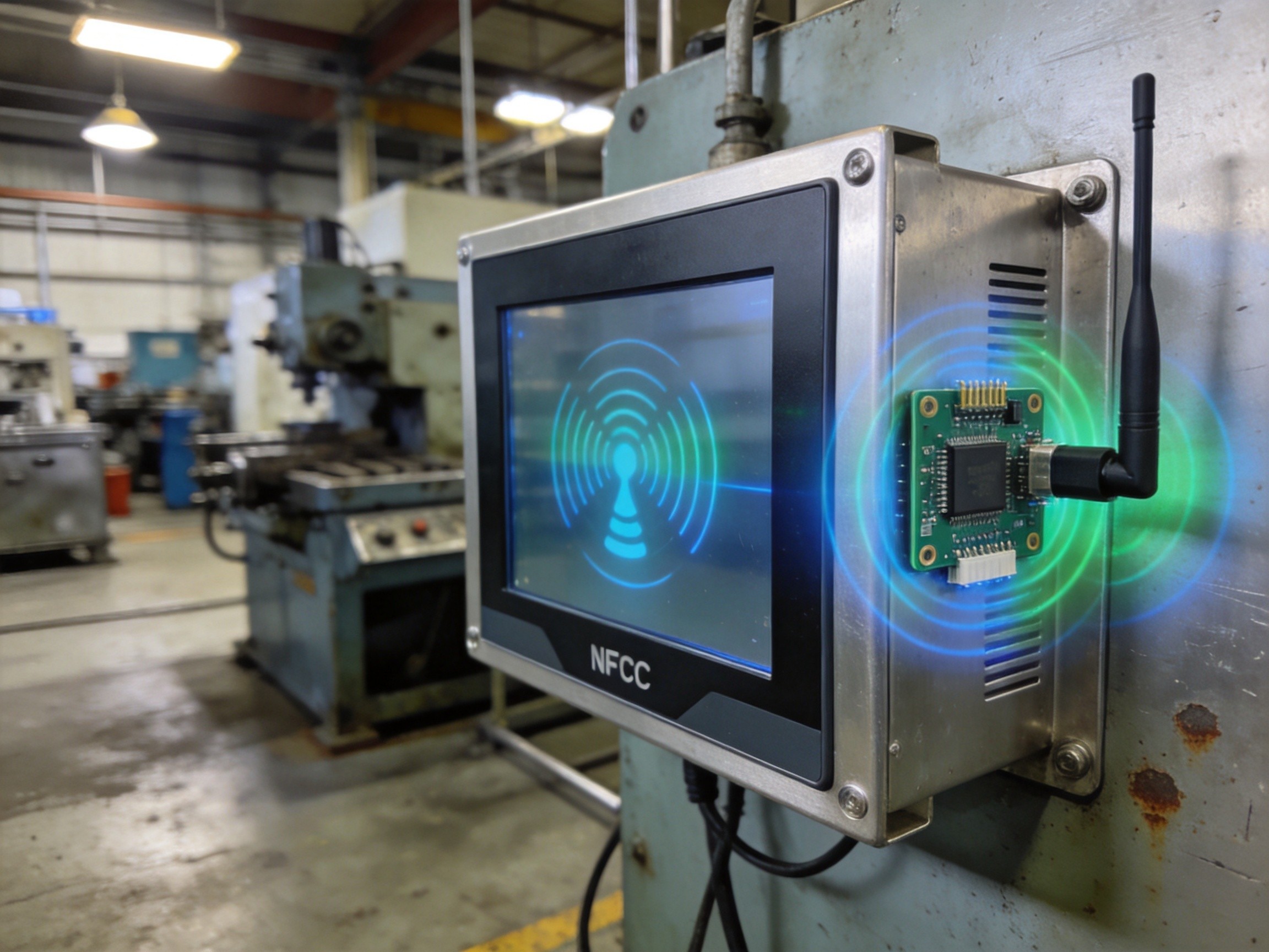
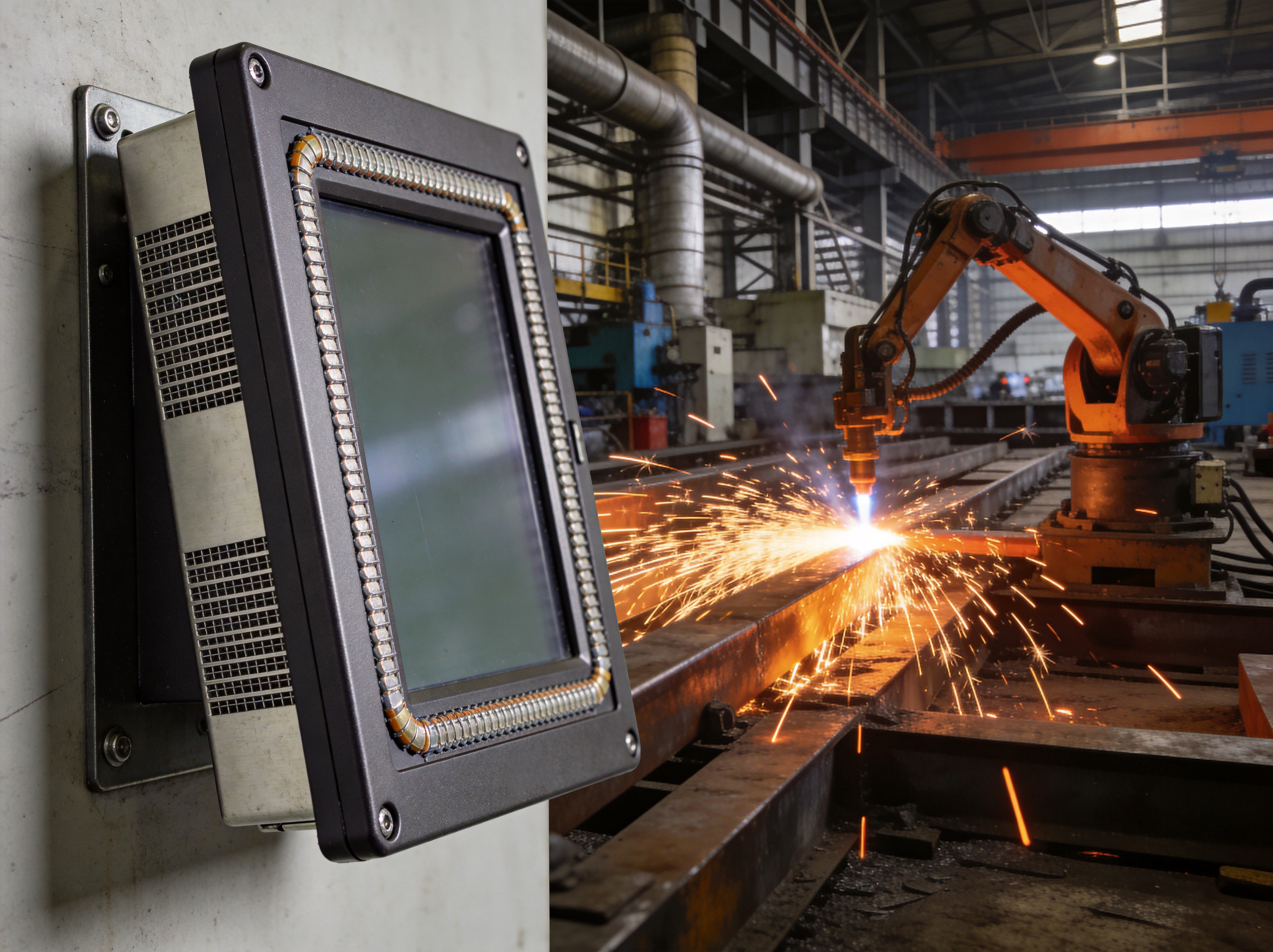
Electromagnetic interference is the silent productivity killer on factory floors. Unlike a bearing failure that announces itself with noise and heat, EMI degradation manifests subtly—erratic sensor readings, intermittent communication dropouts, phantom touch events on display screens—and the troubleshooting path is rarely obvious. In environments saturated with variable frequency drives, arc welding equipment, and high-power motor controllers, industrial panel PCs operate in an electromagnetic storm that would overwhelm commercial-grade electronics within hours. Understanding how proper shielding design, enclosure grounding, and board-level layout practices combine to create interference-immune computing platforms is essential for anyone specifying hardware for electrically noisy industrial environments.
The Physics of EMI: Understanding the Threat
Electromagnetic interference in industrial settings comes in two primary forms: conducted and radiated. Conducted EMI travels along power and signal cables, entering the panel PC through its I/O ports and power supply rails. Radiated EMI couples through the air, penetrating enclosure apertures and inducing unwanted currents in PCB traces. A single three-phase motor start can generate a broadband electromagnetic pulse that saturates nearby unshielded electronics. The panel PC’s vulnerability depends on the effectiveness of its shielding at every ingress point—the enclosure seams, the display bezel interface, the cable entry glands, and the connector backshells. Each of these represents a potential antenna that, if not properly terminated, will funnel interference directly into the system’s sensitive digital circuits.
Gasket Design: The First Line of Defense
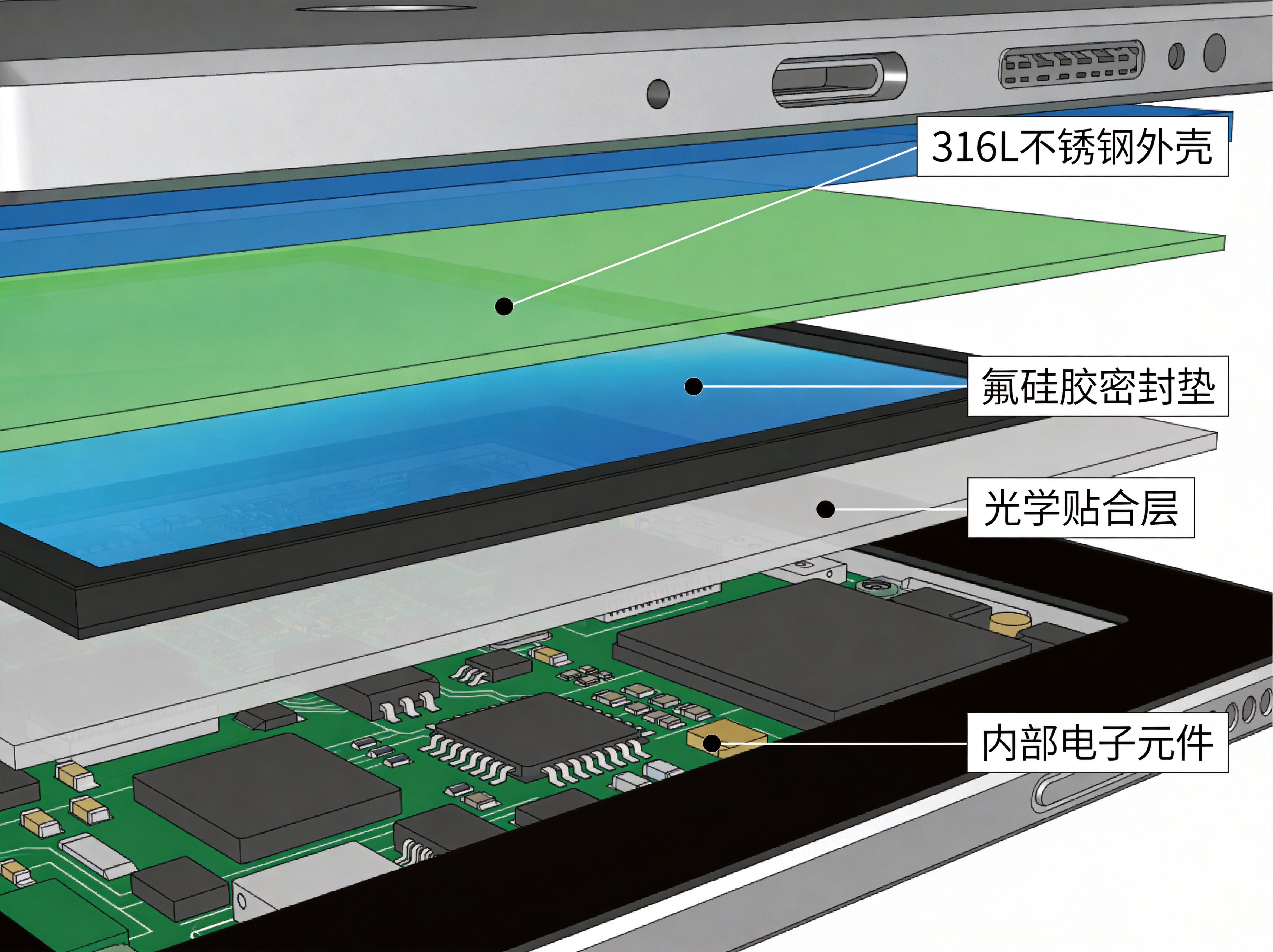
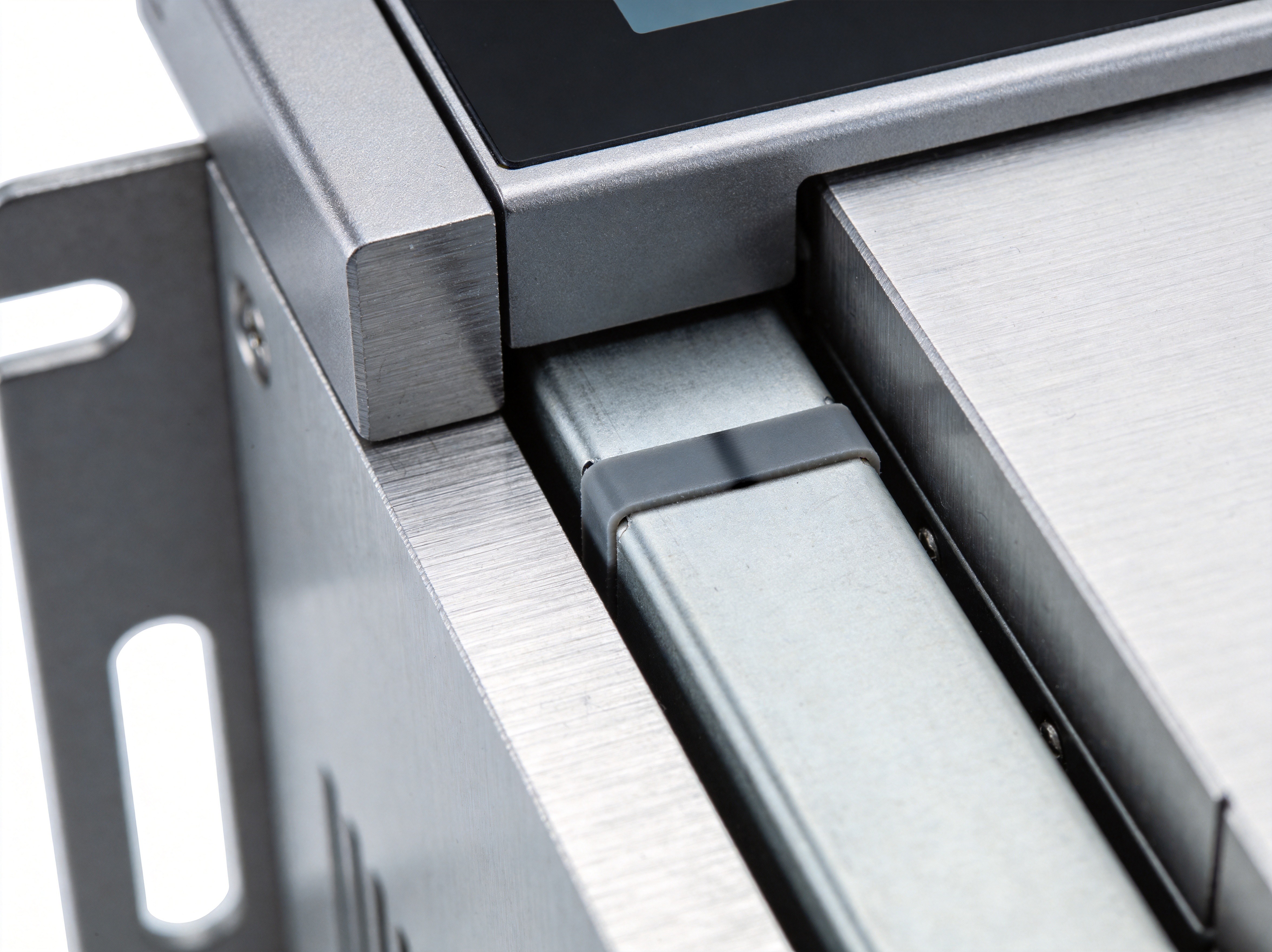
Enclosure gaskets are the most overlooked yet most critical element of EMI shielding. A metal enclosure with a poorly designed gasket is functionally no better than a plastic housing. The gasket must create a continuous, low-impedance electrical path around the entire perimeter of every removable panel and access door. Modern industrial panel PC designs use conductive elastomer gaskets—silicone or fluorosilicone compounds loaded with silver-plated aluminum or nickel-graphite particles—that compress to fill surface irregularities while maintaining conductivity across the full operating temperature range. The gasket compression force, groove geometry, and fastener spacing must be engineered as a system. KOXIAN panel PCs employ precision-machined enclosure interfaces with validated gasket compression profiles that maintain shielding effectiveness above sixty decibels across the critical thirty megahertz to one gigahertz frequency range where most industrial noise sources operate.
Enclosure Grounding: Why the Chassis Connection Matters
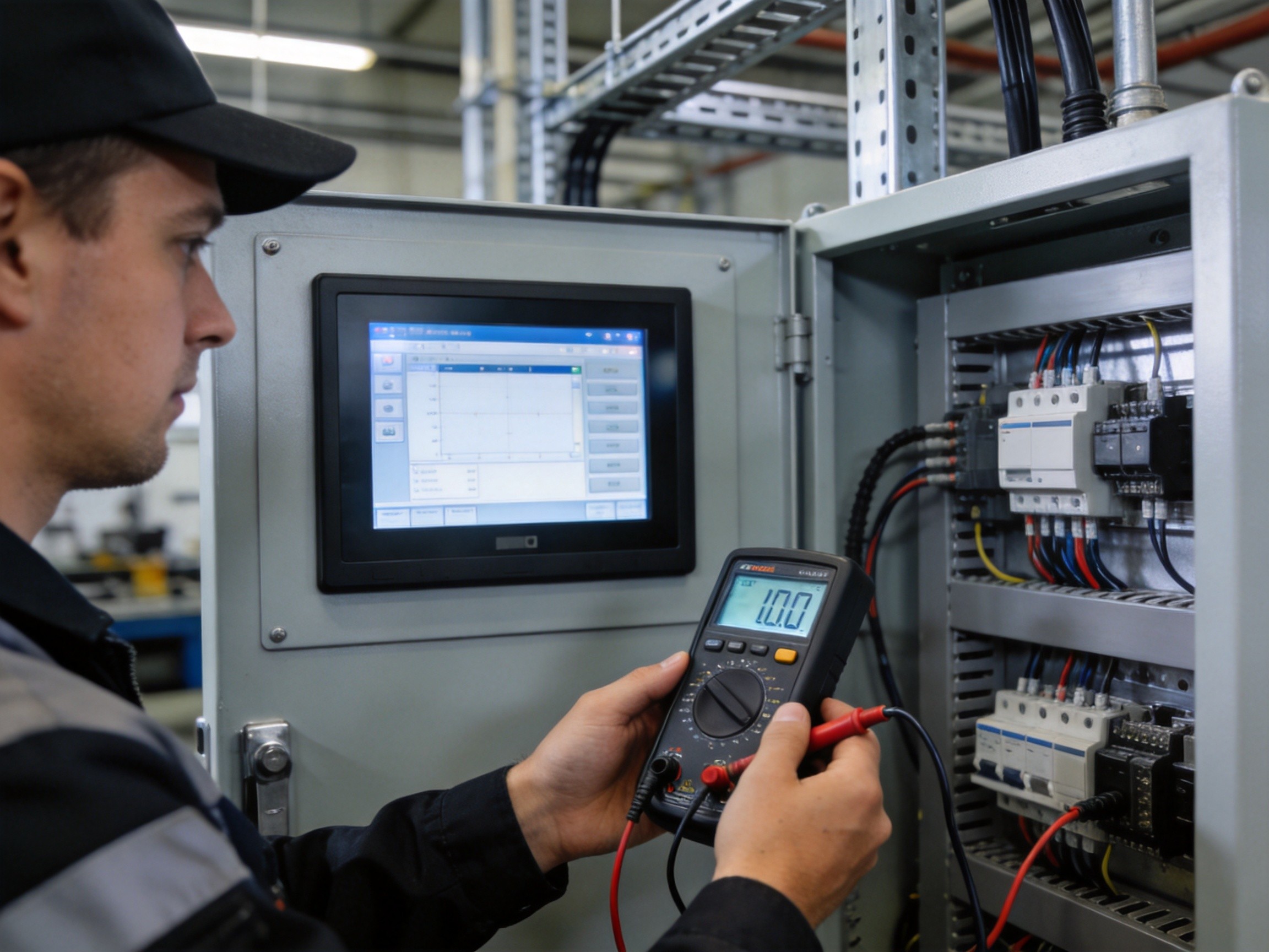
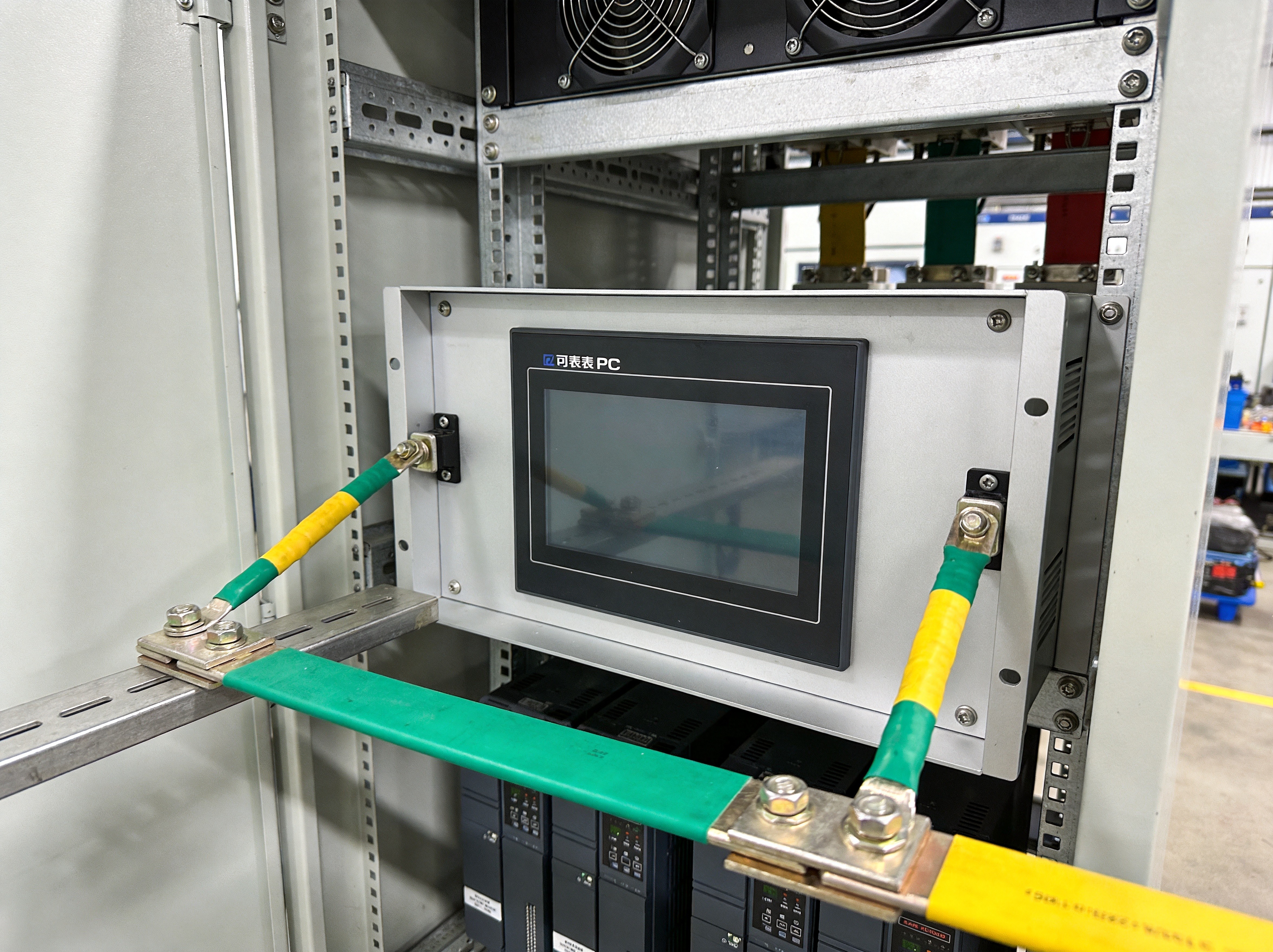
A shielded enclosure that is not properly grounded becomes part of the problem rather than the solution. Without a low-impedance path to earth, the enclosure acts as a re-radiating surface—capturing ambient electromagnetic energy and re-emitting it inside the chassis where it couples directly onto the PCB. The grounding strategy must address both the DC path and the high-frequency impedance. At radio frequencies, a wire that measures near zero ohms on a multimeter can present hundreds of ohms of impedance due to inductance. KOXIAN panel PCs use wide, flat grounding straps and multiple chassis bonding points to minimize high-frequency impedance. The mounting arrangement—whether panel-mounted, VESA-arm, or yoke—must also be considered, as the mechanical interface can inadvertently create ground loops if not designed with single-point grounding principles.
PCB Layout Best Practices for Noise Immunity
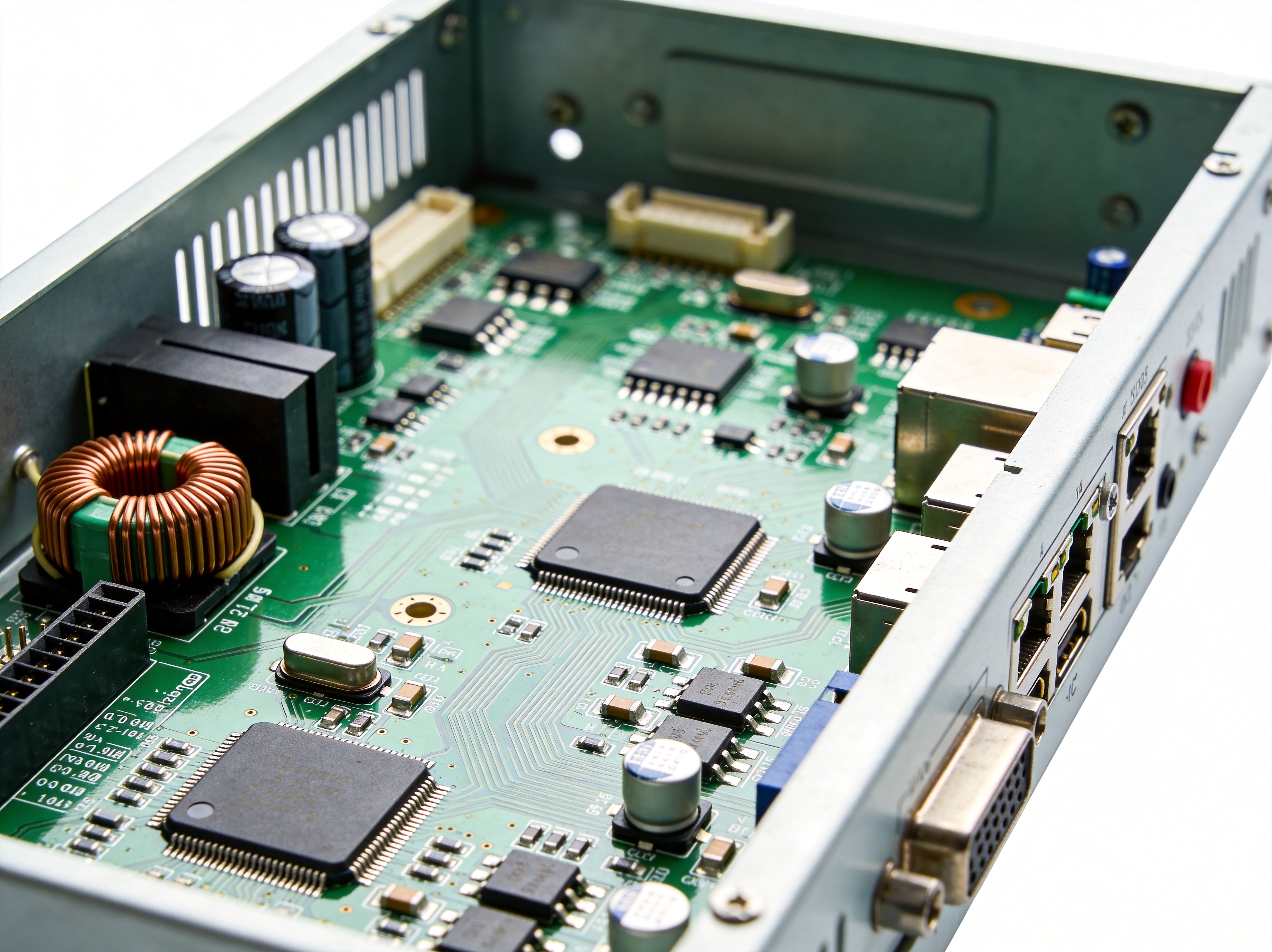
Even with a perfectly shielded enclosure, poor PCB layout can create internal noise problems that degrade system reliability. The fundamental principles are well established but frequently compromised in cost-sensitive designs: maintain unbroken ground planes across all layers, route high-speed digital signals away from board edges, use guard traces around sensitive analog inputs, and keep power supply switching nodes physically compact to minimize radiated emissions. Differential signaling for critical communication interfaces—USB, Ethernet, display connections—provides inherent common-mode noise rejection. The single most important layout decision for industrial panel PCs is the placement and quality of the grounding connections between the PCB, the enclosure, and the I/O connector shells. These bonds must be short, direct, and free of constrictions that would raise impedance at the frequencies of interest.
EMI immunity is not a feature that can be added after the fact with ferrite beads and copper tape. It must be designed into the panel PC from the enclosure gasket selection through to the PCB layer stack. For engineers specifying computing hardware for environments where welding, motor drives, and radio communication equipment operate in close proximity, the shielding design, grounding architecture, and board-level layout practices discussed here should be non-negotiable evaluation criteria. The cost of an EMI-induced production stoppage—lost throughput, scrapped product, and diagnostic hours—dwarfs the incremental investment in properly shielded industrial computing hardware.