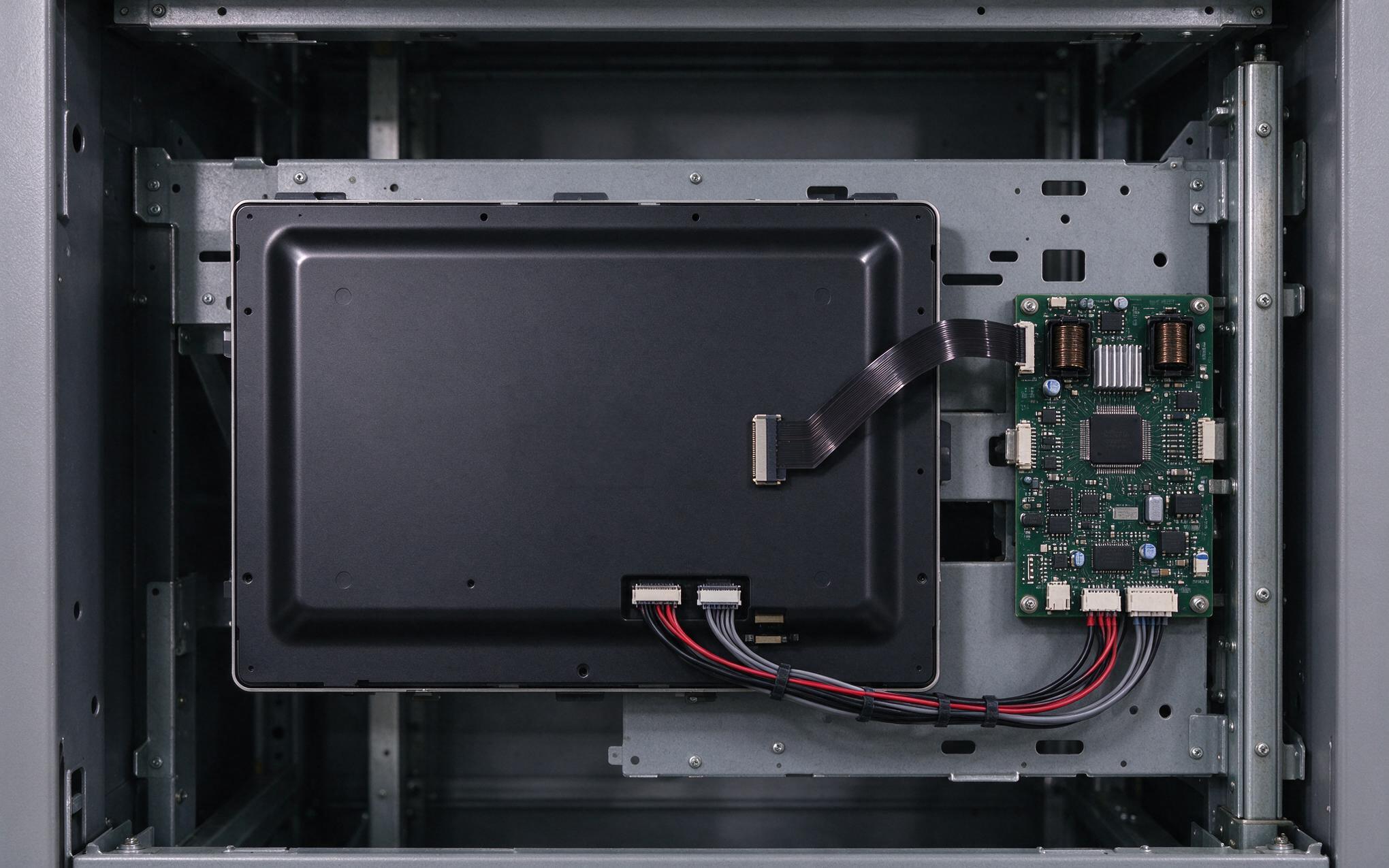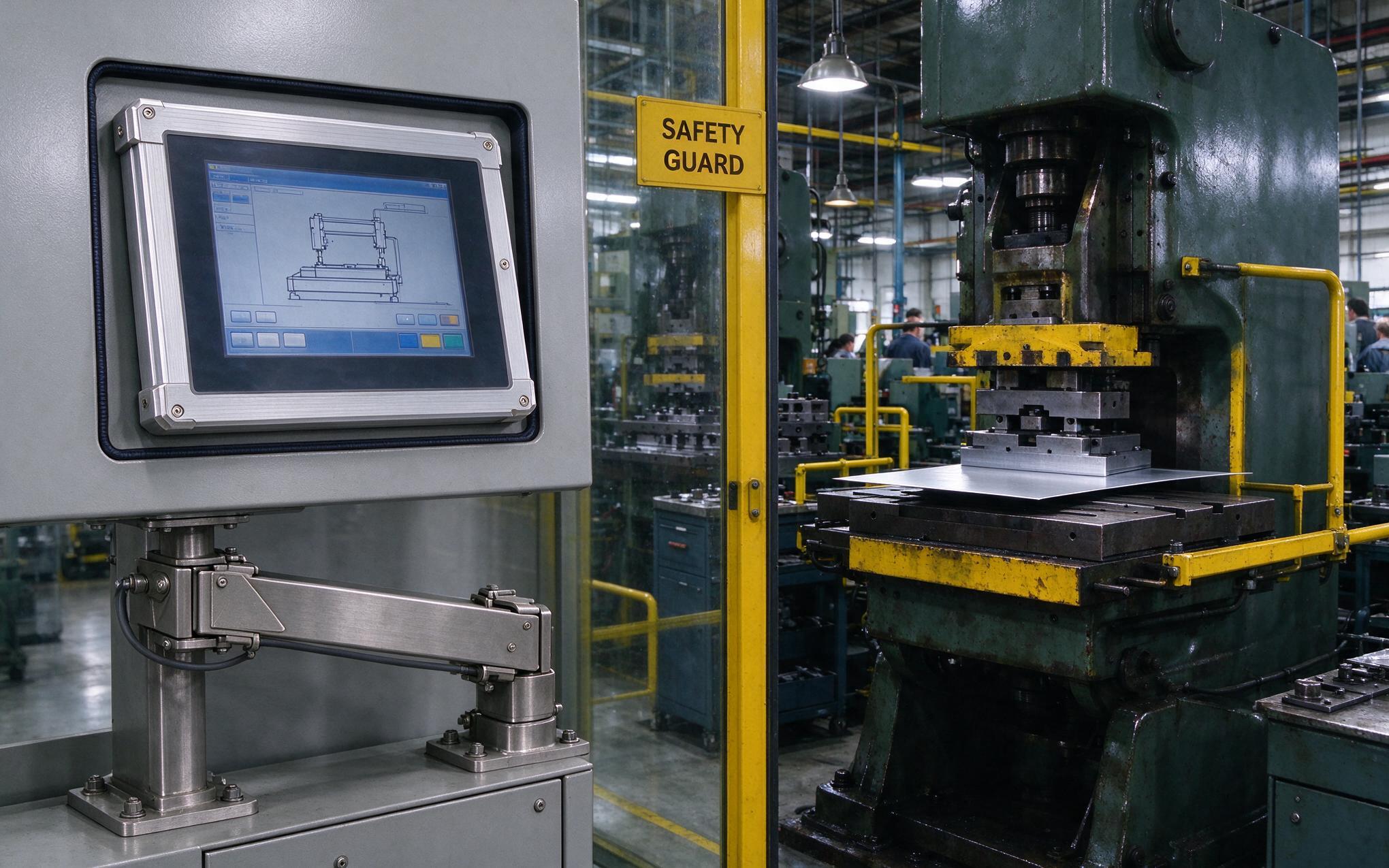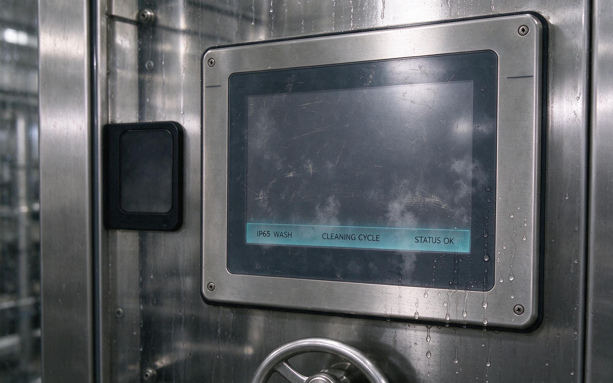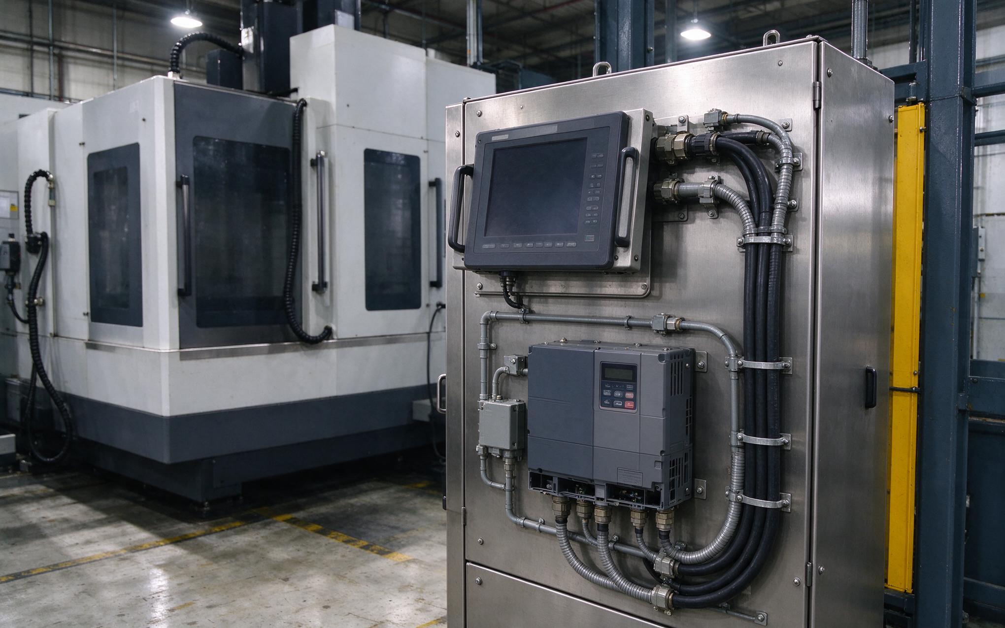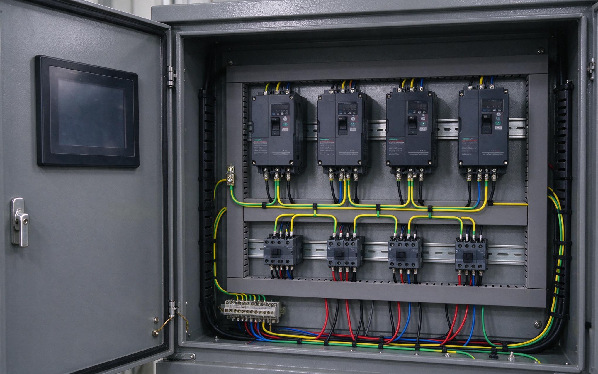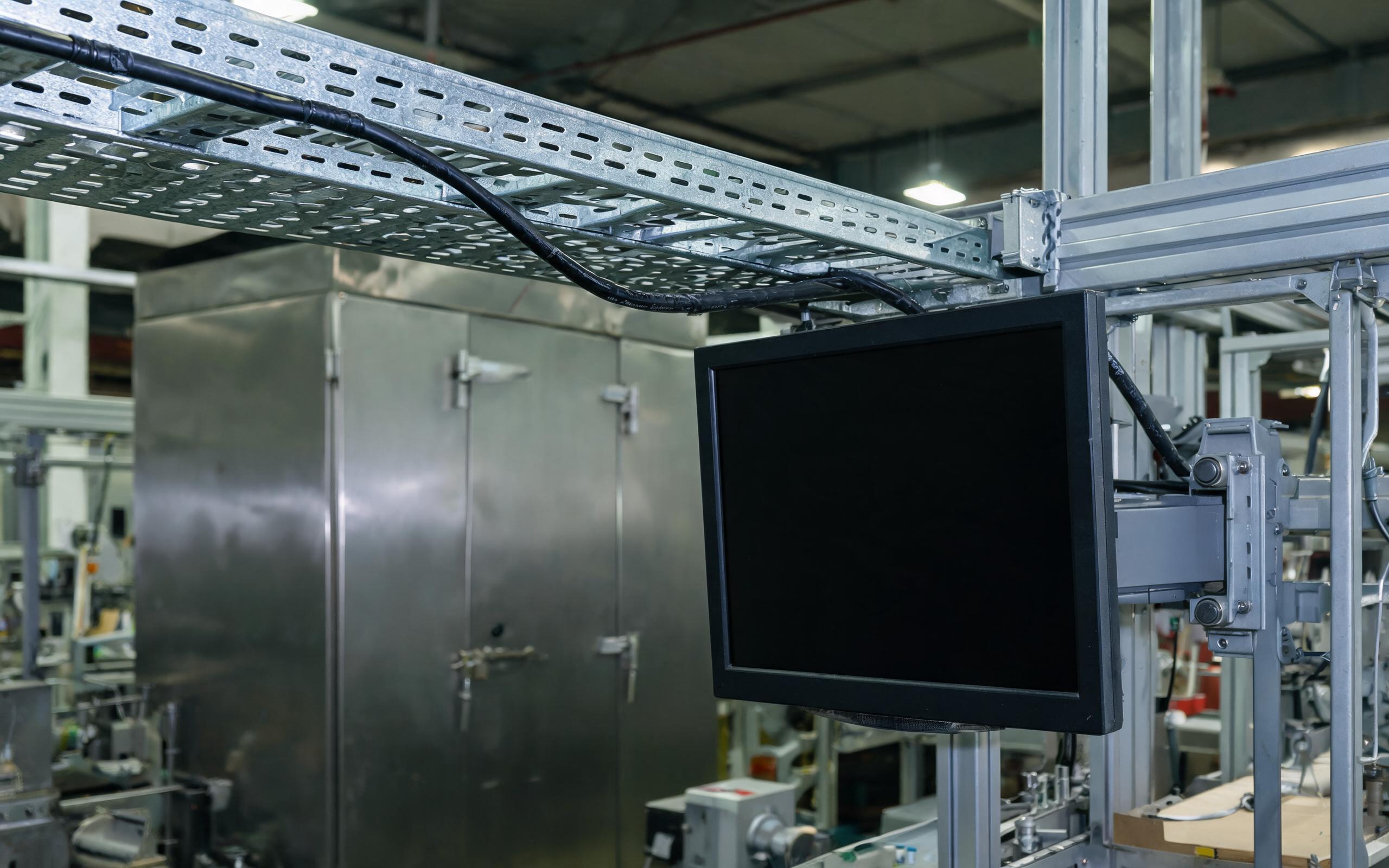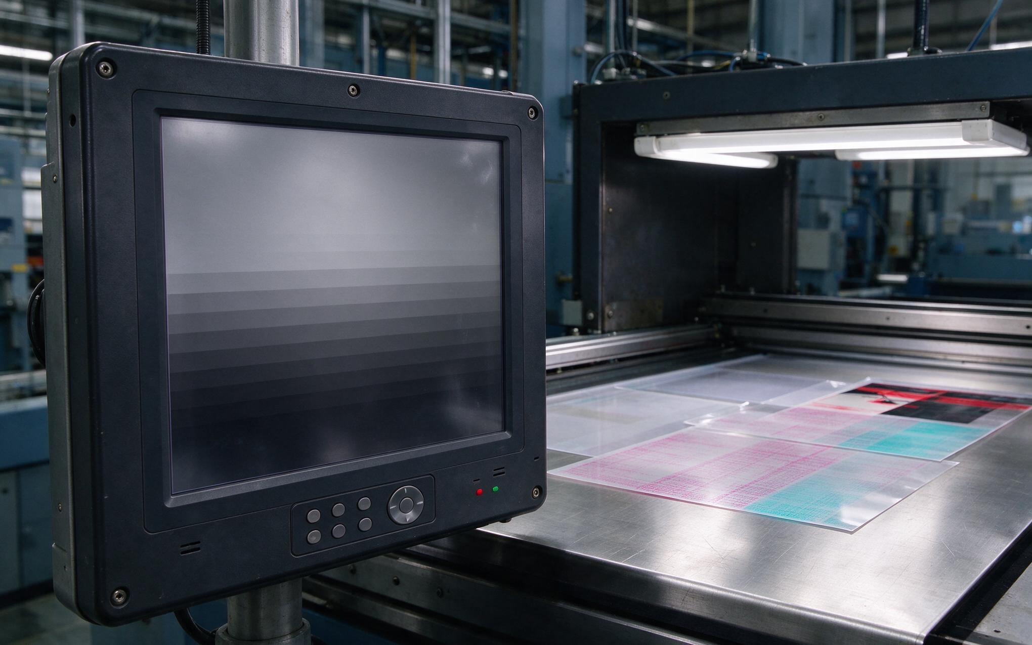
Droplets gather along the lower edge of a panel-mounted display after every washdown cycle while the opposite edge stays dry. The rating on the datasheet covers the panel itself, but the gasket is compressed against sheet metal that may bow across its width, lift at a welded corner, or flex under bolt load. Those deviations, not the seal, are what usually open a path for water. Flatness of the mounting surface is the variable that decides whether an industrial ip65 touch screen performs to its rating once it leaves the factory bench, and it is also the easiest variable to measure before anything gets wet. On a live line, the check takes a minute before commissioning, while the leak it prevents usually surfaces during the busiest shift.

In the Cutout, Seal Load Starts at the Mounting Surface
An IP65 front rating is verified with the panel clamped to a rigid, flat reference frame, so the gasket is compressed evenly around its entire perimeter under the condition the test assumed. A real cabinet door rarely behaves like that frame, because painted steel carries residual stress, light-gauge skins flex, and welds pull corners out of plane. Design approaches such as those used by KOXIAN finish the bezel seating face flat so the panel itself adds no error to that interface. Beyond the bezel, everything the gasket on an industrial ip65 touch screen touches is the door: its flatness, its stiffness, and how evenly the bolts pull it down. Once that surface deviates, identical torque at every screw no longer produces identical compression along the seal.

Measuring Door Bow Under Bolt Loads
Deflection shows up in predictable places: the middle of a wide door, the corner opposite the hinges, and any span left unsupported behind the cutout. Field observations of KOXIAN panels in washdown cells point to the bottom edge as the usual leak zone, where thin skins sag away from the gasket under bolt load and their own weight. Over-torquing to compensate makes it worse by pulling the surrounding area down while the center stays high, a shape no linear gasket can follow. Welded frames bring the mirror image, since heat distortion leaves one edge standing proud and pushes that side of the seal past its design window. None of this appears on a datasheet, because the panel left the factory flat.
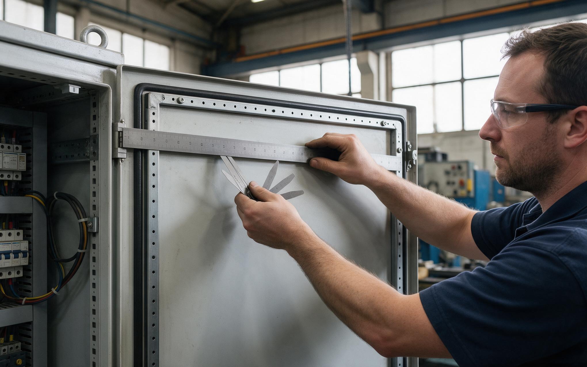
Field Checks With a Straightedge and Feeler Gauge
A straightedge laid across the mounting face in both directions and on both diagonals finds most problems in under a minute. Sight along the gap and quantify deviation with a feeler gauge or shim strip instead of judging by eye, then write down readings at the center and each corner. Shims, a closed-cell backing strip under low spots, and a cross-pattern torque sequence in two passes are the usual corrections when an industrial ip65 touch screen has to mount to a surface that was built long before the panel arrived. Recheck the corners after the initial operating week, because painted steel keeps relaxing and an early reading rarely holds indefinitely.

Supplier Drawings for an Industrial IP65 Touch Screen Seal
Before an order is placed, ask for the flatness callout the gasket design assumes, expressed as a tolerance across the full mounting face rather than a general note. The drawing should also show corner radius, screw pattern, and the compression window the front assembly was validated in, so crews can measure against something concrete. For washdown lines and outdoor cabinets, request confirmation that the seal was qualified against a flat reference plate, along with a written re-torque schedule for the mounting bolts. An industrial ip65 touch screen delivered with those few pages gives the integrator a measurable target and gives the rating a life beyond the factory bench.
The rating on a datasheet describes the panel, while the surface it bolts to decides what happens on site. Flatness, stiffness, and even bolt load are what let a sealed front panel perform the way the test claimed, and all three can be checked with a straightedge before any water is involved. Teams that measure the mounting face, correct what sits out of plane, and recheck after the initial thermal cycle keep the protection they specified. Teams that skip those steps tend to discover the gap at the worst possible moment, after the line is already running.