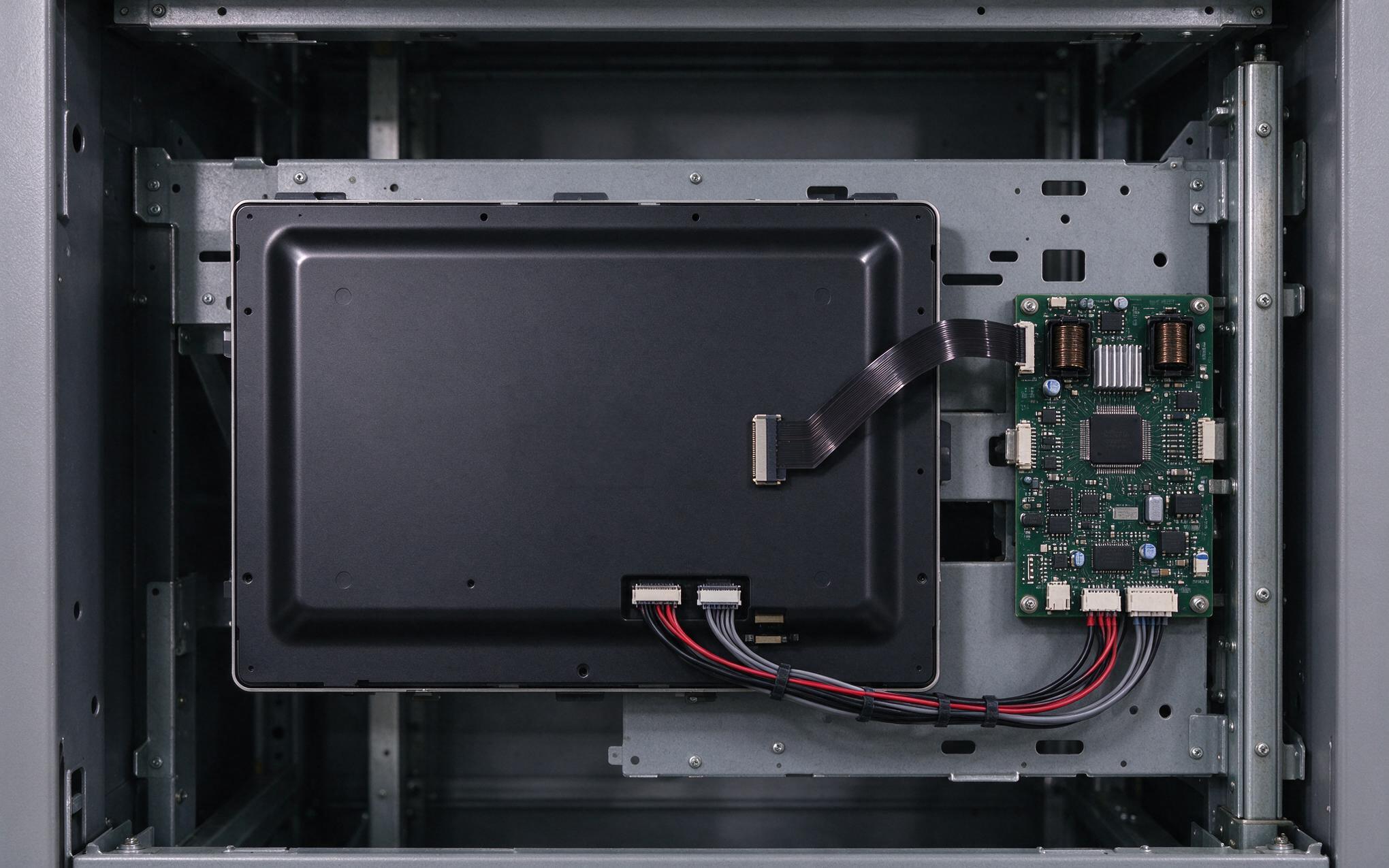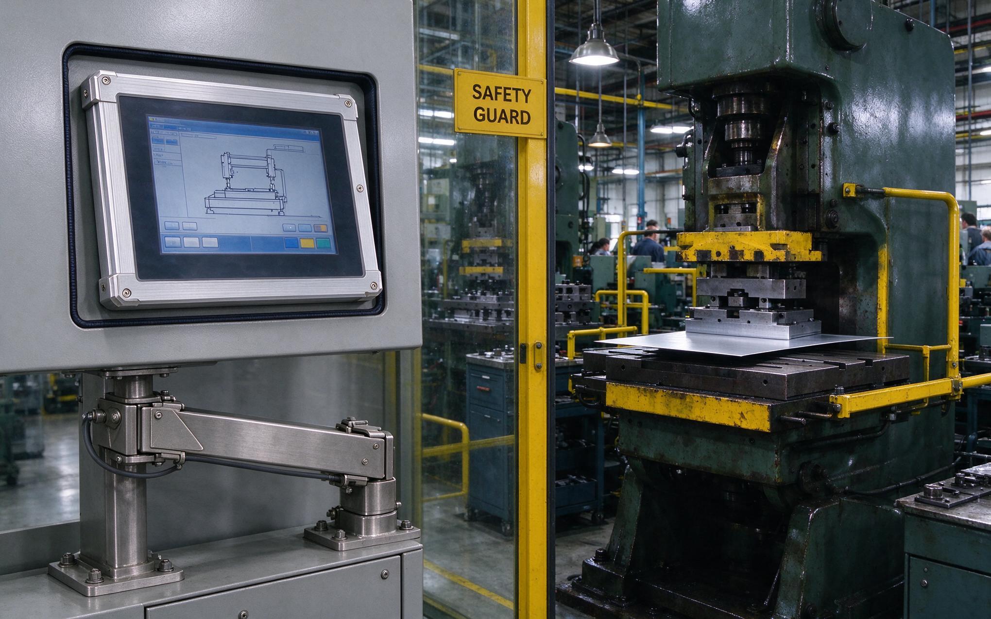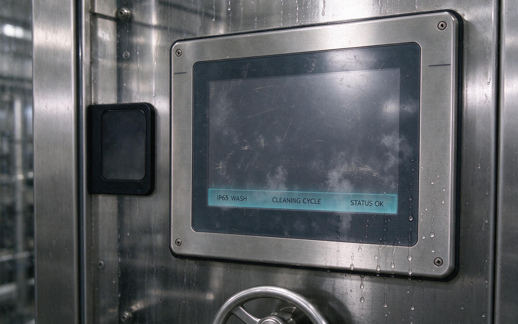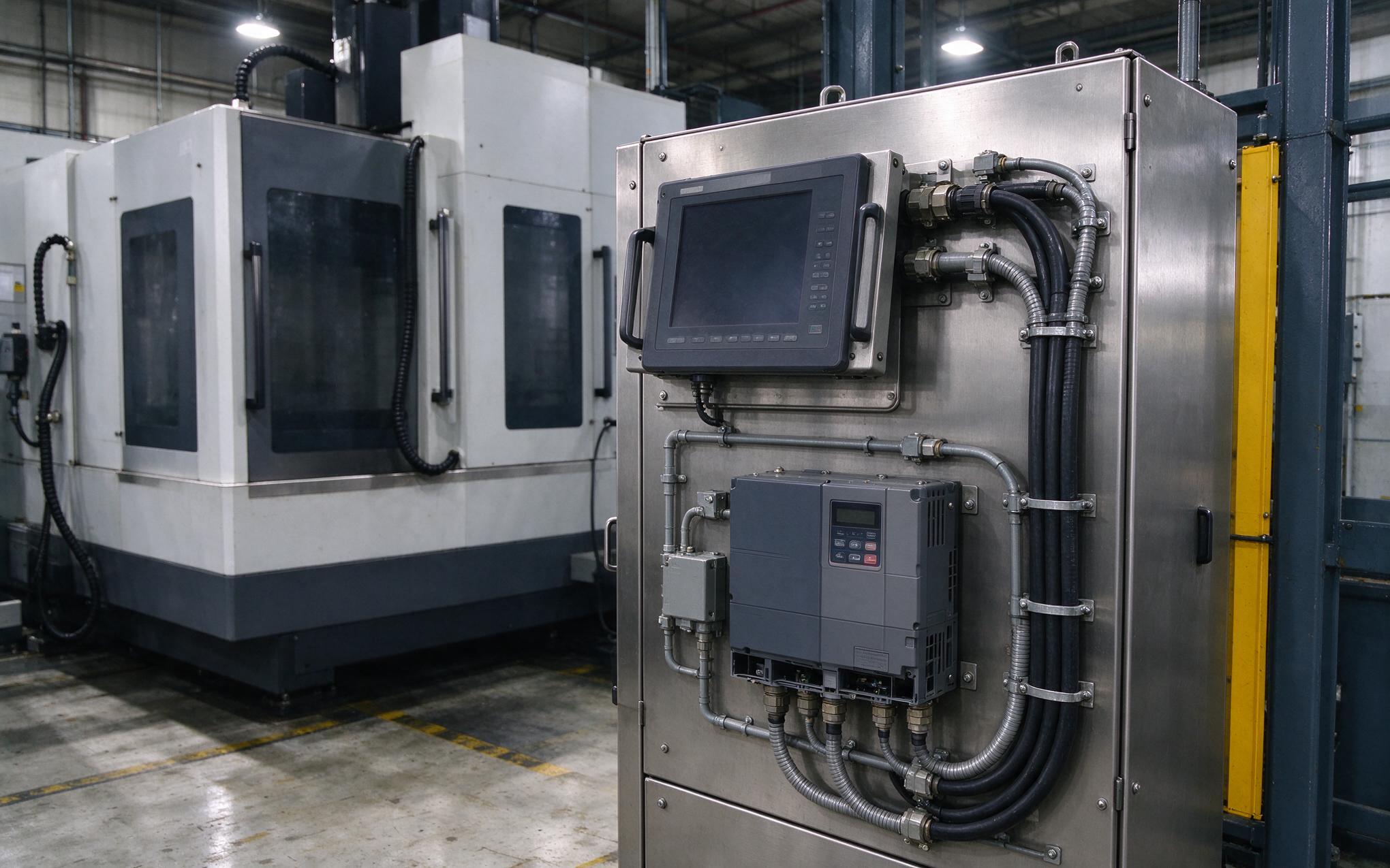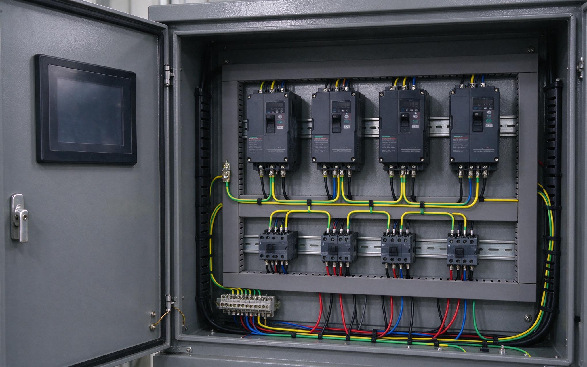
Two numbers decide whether a custom industrial panel PC ever seals at the cabinet face: the width of the sheet metal cutout and the bezel flange that has to press into it. On paper both features look simple. On the shop floor the cutout carries shear variation, brake radius, paint film, and the flatness of a door that was never truly flat, while the flange carries its own profile tolerance. Those errors stack in one direction or the other, and the gasket absorbs whatever is left over. A short tolerance review at the drawing stage costs far less than a leak investigation after the line is running.
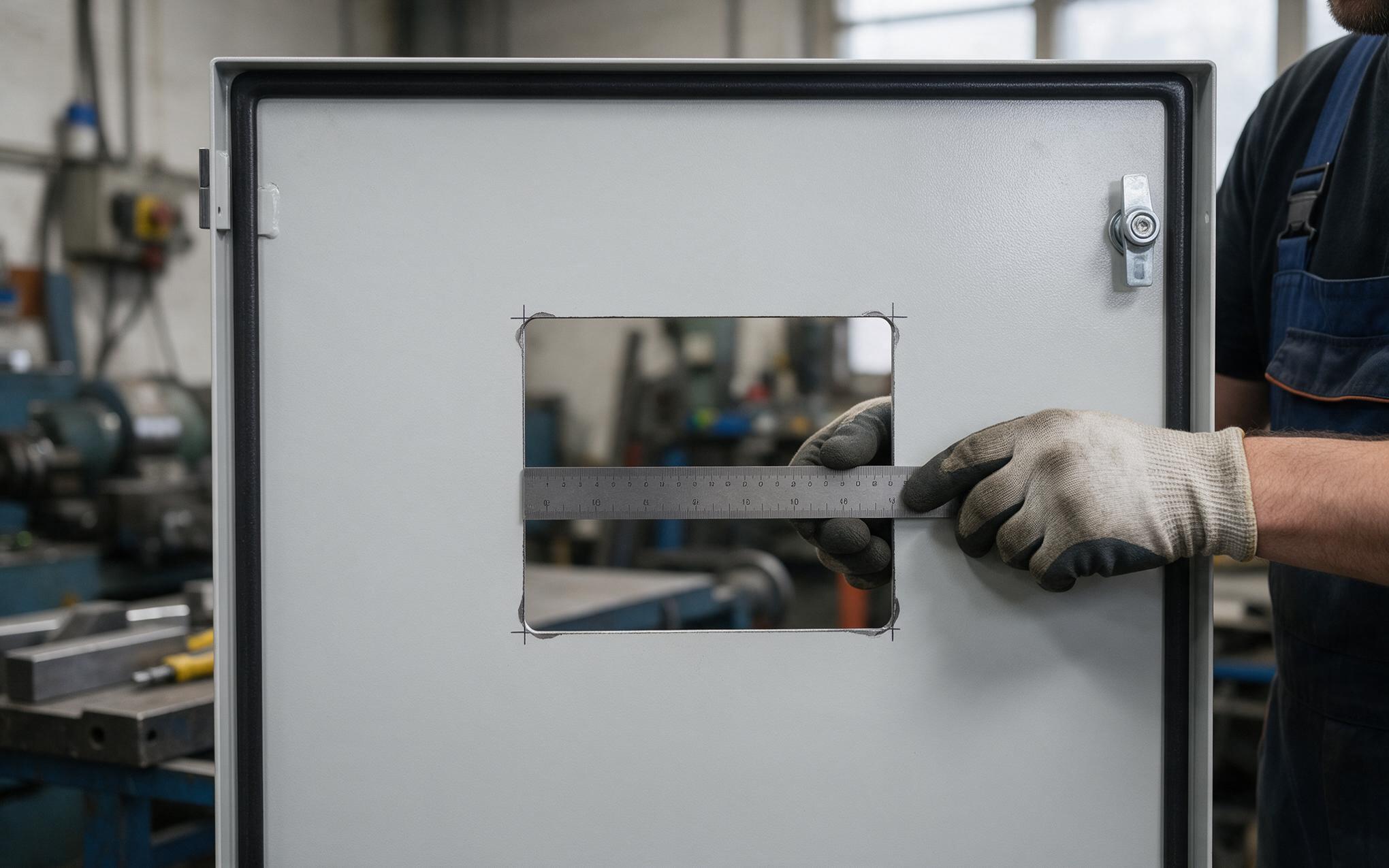
In the Cutout Drawing Before Metal Is Cut
The flange proportions used in the KOXIAN G1 series show how a drawing-level tolerance becomes a repeatable seal at the cabinet face. Treat the cutout as a controlled feature rather than an opening to suit the panel. Width, height, corner radius, and flatness all belong on the drawing with a stated tolerance, referenced to the same edge the mounting clips use. The accumulated stack then includes shear and press-brake variation, paint film, bezel profile tolerance, and thermal growth of the door across its own temperature swing. Working that stack out on paper surfaces conflicts early, while a cutout described only as an approximate opening pushes every decision onto the assembly floor, where there is no time left to argue about intent.
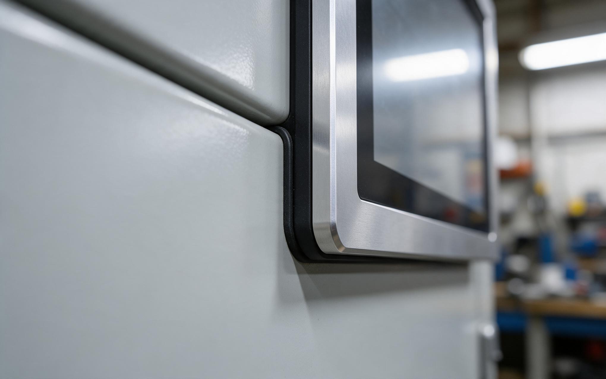
Sizing Compression on a Custom Industrial Panel PC Flange
Compression is the output of that stack and the input to every sealing claim made about the front panel. Too little squeeze leaves a leak path around the gasket, especially where the door has relaxed after the screws were tightened. Too much squeeze bows the flange inward, point-loads the cover glass, and can put visible distortion along the display edge. Corners behave differently from mid-span because the panel resists bending near its fasteners, so one gap reading taken at the center tells only part of the story. For a custom industrial panel PC the practical check is to measure the gap at several points around the frame after torque, then compare those readings against the compression window the gasket supplier publishes for that material and section.
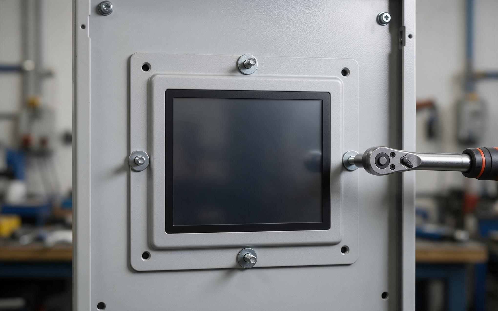
Fastener Spacing and Flange Flatness After Torque
Fastener spacing sets how evenly the flange is pulled against the door. Wide gaps between corner screws let light sheet metal lift between them, opening a gap that no gasket can close by itself. Panel hardware manufacturers, including KOXIAN, hold the flange flat across the fastener pattern so the gasket sees even squeeze instead of a wavy line. Torque sequence matters as much as torque value, so work outward from the center in a crossing pattern and revisit each screw once the gasket has taken its set. Where the door is thin, a backing plate or a formed rib behind the cutout adds stiffness exactly where the pull-up force lands. The same reasoning applies when the custom industrial panel PC drops into a cabinet that was drawn around an older bezel.

How to Prove the Fit Before Line Release
Verification closes the loop before any cabinet reaches the floor. Build a mock cutout from the released drawing, trial-fit the unit, and check gap and flushness at each corner with a feeler gauge or a shallow depth probe. A pressure-sensitive film laid across the gasket line shows where contact is actually made, which settles the question faster than reading a revision note. Assembled units then belong on a spray test to IEC 60529 whenever an ingress rating is claimed, with a repeat check after a thermal cycle because gasket set changes the picture. Record the drawing revision and the measured gap in the build packet so a replacement custom industrial panel PC lines up with the cabinet it was drawn for.
Tolerance work pays back at installation time. When the cutout, the flange, and the fastener pattern are treated as one stack instead of three separate drawings, gasket compression lands where the design intended and the seal holds through washdown, vibration, and temperature swings. Teams that document the cutout tolerance, log the measured gap, and revisit both whenever a bezel profile changes spend their schedule on commissioning rather than on leak hunts. The drawing review takes an afternoon; the field investigation takes a shutdown.